
herunterladen
© 2006 Microchip Technology Inc. DS01035A-page 1
AN1035
INTRODUCTION
When designing embedded microcontroller
applications, one of the greatest challenges can be the
creation of the power supply for the microcontroller.
Particularly when the only supply voltage available is
significantly higher than the microcontroller’s maximum
V
DD.
To help simplify embedded design, Microchip has
introduced a new feature in a select group of new
microcontroller offerings, a 5V shunt regulator. This
on-chip regulator allows the microcontroller to operate
from a wide variety of supply voltages. As an added
bonus, the shunt regulator topology also allows the
connection of other circuitry, external to the
microcontroller, to be powered by the V
DD pin.
This application note discusses the design of power
supply circuits using the new shunt regulator, and
presents some Tips ‘n Tricks for extending the
regulator’s capabilities.
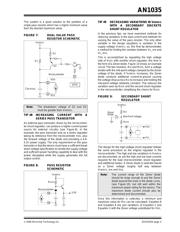
THEORY OF OPERATION
A shunt regulator generates a specific supply voltage
by creating a voltage drop across a pass resistor R
SER.
The voltage at the V
DD pin of the microcontroller is
monitored and compared to an internal voltage refer-
ence. The current through the resistor is then adjusted,
based on the result of the comparison, to produce a
voltage drop equal to the difference between the supply
voltage V
UNREG and the VDD of the microcontroller.
The advantage to a shunt regulator is that the supply
voltage, V
UNREG, is only limited by the power dissipa-
tion and breakdown voltage of the external resistor,
RSER, not the power or breakdown characteristics of
the regulator. The challenge in designing a shunt
regulator circuit is choosing an appropriate value for
the resistor such that the range of currents over which
the regulator has control will produce the correct
voltage drop needed to produce a 5.0 V
DC supply.
So, all we really need to know to design with a shunt
regulator is Ohm’s Law. The problem is that the supply
voltage, VUNREG, is not constant and neither is the load
current. In addition, the range of current over which the
regulator has control, is also limited. So the choice of
R
SER really becomes a balancing act, trying to find a
resistance that will meet all three requirements.
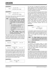
FIGURE 1: SHUNT REGULATOR
BLOCK DIAGRAM
DESIGN
The best place to start in the design process is to
catalog the variations possible in the supply voltage
and the load current. For our purposes, the following
definitions will be used:
•V
U_MIN is the minimum supply voltage to the
system.
•V
U_MAX is the maximum supply voltage to the
system.
•I
LOAD_MIN is the minimum load current, excluding
the regulator.
•I
LOAD_MAX is the maximum load current,
excluding the regulator.
Given these values, it is now possible to determine the
minimum and maximum pass resistor values for the
circuit. Equation 1 and Equation 2 are used to calculate
these values.
Author: Keith Curtis
Microchip Technology Inc.
Note: The constant 5.0 refers to the VDD voltage
of the regulator, the 4 mA constant is the
minimum regulation current for the regula-
tor and the 50 mA constant is the
maximum regulation current for the
regulator.
Feedback
VDD
VSS
CBYPASS
RSER
VUNREG
ISUPPLY
ISHUNT
ILOAD
Designing with HV Microcontrollers
Verzeichnis