
herunterladen
© 2009 Microchip Technology Inc. DS01298A-page 1
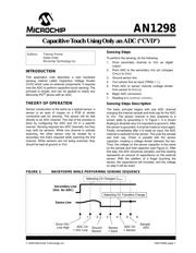
AN1298
INTRODUCTION
This application note describes a new hardware
sensing method called Capacitive Voltage Divider
(CVD) which uses no external components. It requires
only the ADC to perform capacitive touch sensing. The
principle is simple, and can be applied to nearly any
Microchip PIC
®
device with an ADC.
THEORY OF OPERATION
Sensor construction is the same as a typical sensor; a
sensor is an area of copper on a PCB or similar
conductive pad for sensing. The sensor will be tied
directly to an ADC channel. The rest of the process is
done by configuring the ADC and I/O in a specific
manner. Sensing requires two ADC channels, but they
may both be sensors. While one channel is actively
scanning, the other sensor may be reused for a
secondary line that’s required while scanning the first
channel. While sensors are not being scanned, they
should be kept at ground or V
DD.
Sensing Steps
To perform the sensing, do the following:
1. Drive secondary channel to V
DD as digital
output.
2. Point ADC to the secondary V
DD pin (charges
C
HOLD to VDD).
3. Ground sensor line.
4. Turn sensor line as input (TRISx = 1).
5. Point ADC to sensor channel (voltage divider
from sensor to CHOLD).
6. Begin ADC conversion.
7. Reading is in ADRESH:ADRESL.
Sensing Steps Description
The basic principle begins with one ADC channel
charging the internal sample-and-hold cap for the ADC
to V
DD. The sensor channel is then prepared to a
known state by grounding it. In Figure 1, it is shown
floating to illustrate why it is important to ground it. After
the sensor is grounded, it must be made an input again.
Finally, immediately after it is made an input, the ADC
channel is switched to the sensor. This puts the sample
and hold cap, Chold, in parallel with the sensor
capacitor, creating a voltage divider between the two.
Thus, the voltage on the sensor capacitor is the same
on the sample and hold capacitor (see Figure 2). After
this step, the ADC should be sampled, and the reading
represents an amount of capacitance on the external
sensor. With the addition of a finger touching the
sensor, the capacitance will increase, and the voltage
on step 5 will be lower.
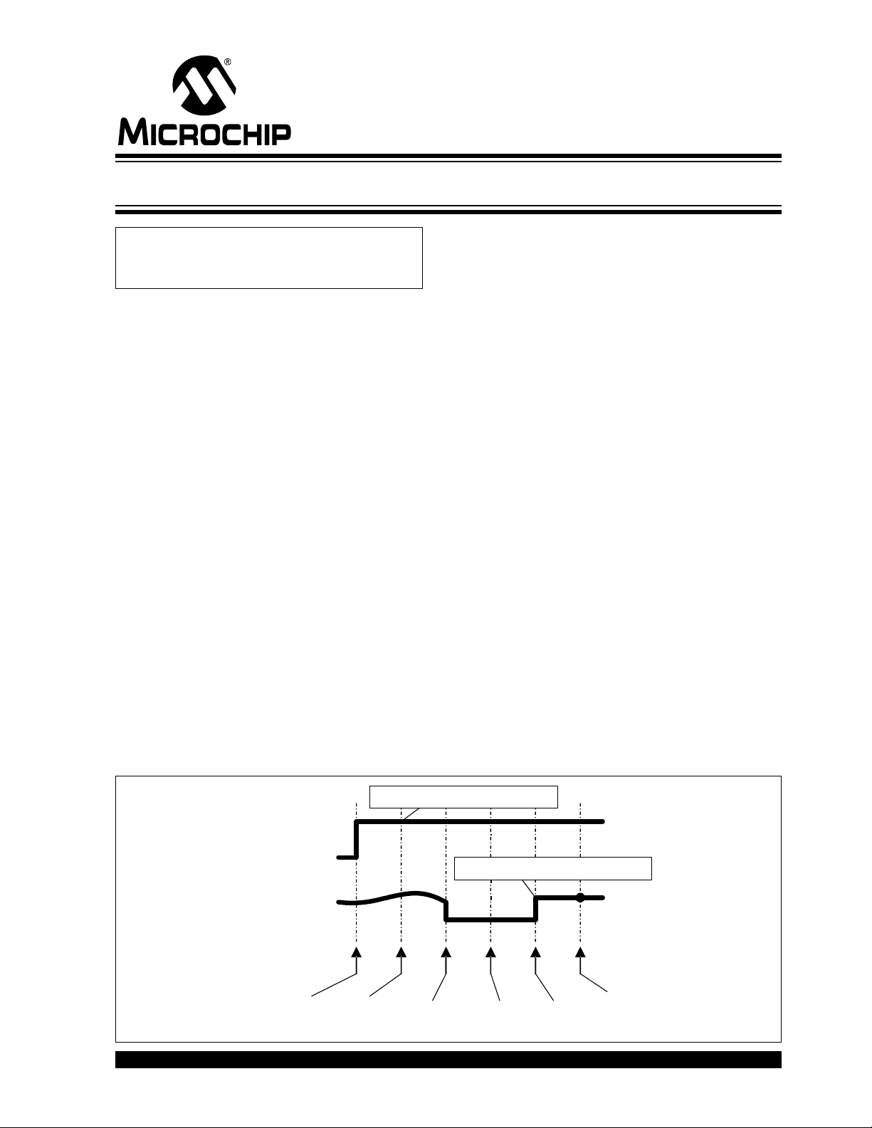
FIGURE 1: WAVEFORMS WHILE PERFORMING SENSING SEQUENCE
Authors: Thomas Perme
Dieter Peter
Microchip Technology Inc.
Secondary Line
(V
DD
for ADC)
Sense Line
1 2 3 4 5 6
Drive V
DD
Line High
ADC Ch
= V
DD
Line
Ground
Sensor
Sensor
= Input
ADC Ch
= Sensor
Sample
ADC
Selecting Ch Transfers Charge
Selecting Ch Charges C
HOLD
Capacitive Touch Using Only an ADC (“CVD”)