

herunterladen
Semiconductor Components Industries, LLC, 2002
February, 2002 – Rev. 0
1 Publication Order Number:
NTD80N02/D
NTD80N02
Advance Information
Power MOSFET
80 Amps, 24 Volts
N–Channel DPAK
Designed for low voltage, high speed switching applications in
power supplies, converters and power motor controls and bridge
circuits.
Typical Applications
• Power Supplies
• Converters
• Power Motor Controls
• Bridge Circuits
MAXIMUM RATINGS (T
J
= 25°C unless otherwise noted)
Rating Symbol Value Unit
Drain–to–Source Voltage V
DSS
24 Vdc
Gate–to–Source Voltage – Continuous V
GS
±20 Vdc
Drain Current – Continuous @ T
A
= 25°C
Drain Current – Single Pulse (t
p
= 10 µs)
I
D
I
DM
80*
200
Adc
Total Power Dissipation @ T
A
= 25°C P
D
75 Watts
Operating and Storage
Temperature Range
T
J
, T
stg
–55 to
150
°C
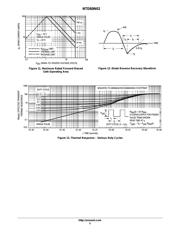
Single Pulse Drain–to–Source Avalanche
Energy – Starting T
J
= 25°C
(V
DD
= 24 Vdc, V
GS
= 10 Vdc,
I
L
= 17 Apk, L = 5.0 mH, R
G
= 25 Ω)
E
AS
733 mJ
Thermal Resistance
– Junction–to–Case
– Junction–to–Ambient (Note 1)
– Junction–to–Ambient (Note 2)
R
θJC
R
θJA
R
θJA
1.65
67
120
°C/W
Maximum Lead Temperature for Soldering
Purposes, 1/8″ from case for 10 seconds
T
L
260 °C
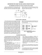
1. When surface mounted to an FR4 board using 1″ pad size,
(Cu Area 1.127 in
2
).
2. When surface mounted to an FR4 board using the minimum recommended
pad size, (Cu Area 0.412 in
2
).
*Chip current capability limited by package.
This document contains information on a new product. Specifications and information
herein are subject to change without notice.
80 AMPERES
24 VOLTS
R
DS(on)
= 5.0 mΩ (Typ.)
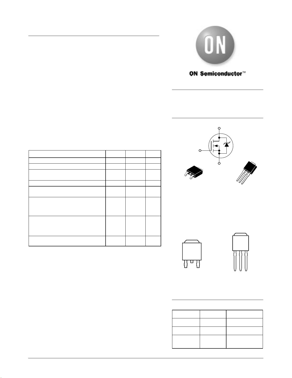
Device Package Shipping
ORDERING INFORMATION
NTD80N02 DPAK 75 Units/Rail
http://onsemi.com
N–Channel
D
S
G
NTD80N02T4 DPAK 2500 Tape & Reel
NTD80N02–1 DPAK
Straight Lead
75 Units/Rail
CASE 369A
DPAK
(Bend Lead)
STYLE 2
MARKING DIAGRAMS
& PIN ASSIGNMENTS
Y = Year
WW = Work Week
80N02 = Device Code
YWW
80
N02
3
Source
2
Drain
4
Drain
1
2
3
4
YWW
80
N02
1
Gate
3
Source
2
Drain
4
Drain
1
2
3
4
CASE 369
DPAK
(Straight Lead)
STYLE 2
1
Gate
Verzeichnis
- ・ Konfiguration des Pinbelegungsdiagramms on Seite 1
- ・ Abmessungen des Paketumrisses on Seite 8 Seite 9
- ・ Teilenummerierungssystem on Seite 1 Seite 12
- ・ Markierungsinformationen on Seite 1
- ・ Typisches Anwendungsschaltbild on Seite 1
- ・ Technische Daten on Seite 1
- ・ Anwendungsbereich on Seite 1 Seite 6
- ・ Elektrische Spezifikation on Seite 2