
herunterladen
© Semiconductor Components Industries, LLC, 2014
October, 2014 − Rev. 13
1 Publication Order Number:
NCP380/D
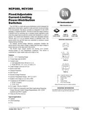
NCP380, NCV380
Fixed/Adjustable
Current‐Limiting
Power‐Distribution
Switches
The NCP380 is a high side power-distribution switch designed for
applications where heavy capacitive loads and short-circuits are likely
to be encountered. The device includes an integrated 55 mW (DFN
package), P-channel MOSFET. The device limits the output current to
a desired level by switching into a constant-current regulation mode
when the output load exceeds the current-limit threshold or a short is
present. The current-limit threshold is either user adjustable between
100 mA and 2.1 A via an external resistor or internally fixed. The
power-switch rise and fall times are controlled to minimize current
ringing during switching.
An internal reverse-voltage detection comparator disables the
power-switch if the output voltage is higher than the input voltage to
protect devices on the input side of the switch.
The FLAG
logic output asserts low during over current,
reverse-voltage or over temperature conditions. The switch is
controlled by a logic enable input active high or low.
Features
• 2.5 V – 5.5 V Operating Range
• 70 mW High-side MOSFET
• Current Limit:
♦ User adjustable from 100 mA to 2.1 A
♦ Fixed 500 mA, 1 A, 1.5 A, 2 A and 2.1 A
• Under Voltage Lock-out (UVLO)
• Built-in Soft-start
• Thermal Protection
• Soft Turn-off
• Reverse Voltage Protection
• Junction Temperature Range: −40°C to 125°C
• Enable Active High or Low (EN or EN)
• Compliance to IEC61000−4−2 (Level 4)
♦ 8.0 kV (Contact)
♦ 15 kV (Air)
• UL Listed − File No. E343275
• NCV Prefix for Automotive and Other Applications Requiring
Unique Site and Control Change Requirements; AEC−Q100
Qualified and PPAP Capable
• These are Pb-Free Devices
Typical Applications
• Laptops
• USB Ports/Hubs
• TVs
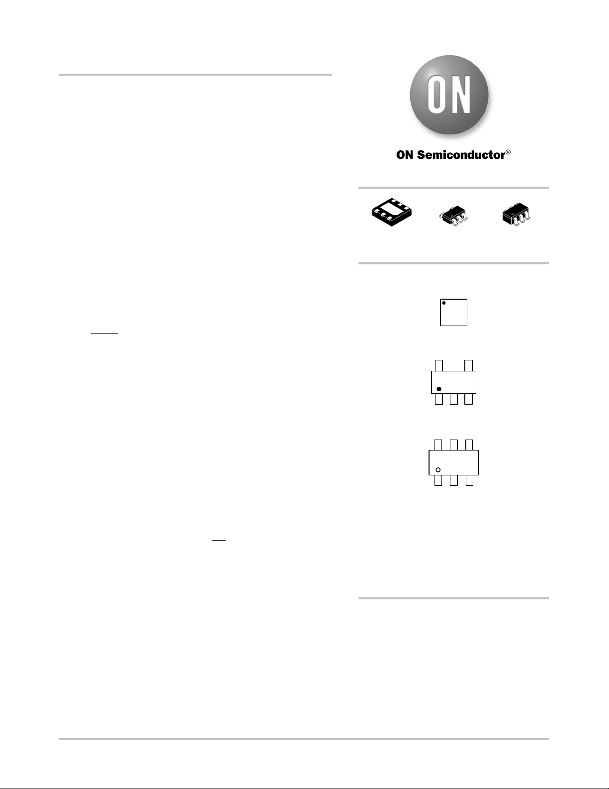
UDFN6
CASE 517AB
MARKING DIAGRAMS
http://onsemi.com
XX M
1
2
3
6
5
4
TSOP−5
CASE 483
1
5
XXXAYWG
G
(Note: Microdot may be in either location)
TSOP−6
CASE 318G
XXX = Specific Device Code
A =Assembly Location
M = Date Code
Y = Year
W = Work Week
G = Pb−Free Package
XXXAYWG
G
1
See detailed ordering and shipping information in the package
dimensions section on page 20 of this data sheet.
ORDERING INFORMATION
UDFN6
TSOP−5
TSOP−6
Verzeichnis
- ・ Konfiguration des Pinbelegungsdiagramms on Seite 2
- ・ Abmessungen des Paketumrisses on Seite 21 Seite 22 Seite 23
- ・ Paket-Footprint-Pad-Layout on Seite 21 Seite 22 Seite 23
- ・ Teilenummerierungssystem on Seite 1 Seite 20 Seite 23
- ・ Markierungsinformationen on Seite 1 Seite 20 Seite 23
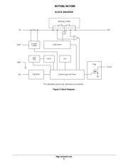
- ・ Blockdiagramm on Seite 6
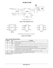
- ・ Typisches Anwendungsschaltbild on Seite 1 Seite 2 Seite 19
- ・ Beschreibung der Funktionen on Seite 2 Seite 15
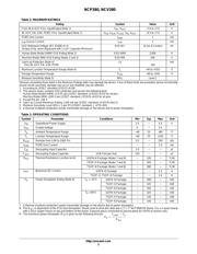
- ・ Technische Daten on Seite 20
- ・ Anwendungsbereich on Seite 1 Seite 20
- ・ Elektrische Spezifikation on Seite 4 Seite 5
- ・ Teilenummernliste on Seite 3