
herunterladen
© Semiconductor Components Industries, LLC, 2014
December, 2014 − Rev. 1
1 Publication Order Number:
AND8353/D
AND8353/D
Implementing Cost
Effective and Robust Power
Factor Correction with the
NCP1607
Introduction
The NCP1607 is a voltage mode power factor correction
(PFC) controller designed to drive cost-effective converters
to meet input line harmonic regulations. The device operates
in Critical Conduction Mode (CRM) for optimal
performance in applications up to about 300 W. Its voltage
mode scheme enables it to obtain unity power factor without
the need for a line sensing network. The output voltage is
accurately controlled with a built in high precision error
amplifier. The controller also implements a comprehensive
array of safety features for robust designs.
This application note describes the design and
implementation of a 400 V, 100 W, CRM Boost PFC
converter using the NCP1607. The converter exhibits high
power factor, low standby power dissipation, high active
mode efficiency, and a variety of protection features.
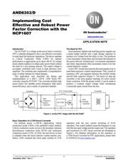
The Need for PFC
Most electronic ballasts and switching power supplies use
a diode bridge rectifier and a bulk storage capacitor to
produce a dc voltage from the utility ac line. This produces
a non-sinusoidal current draw and increases the demand on
the power delivery infrastructure. Government regulations
and utility requirements often necessitate control over line
current harmonic content.
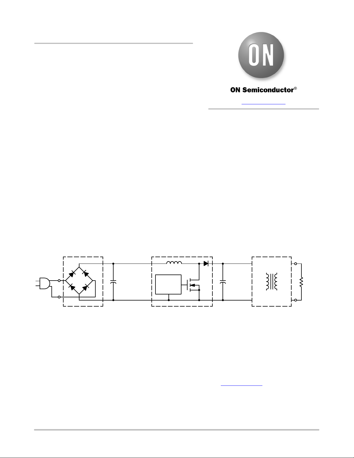
Active PFC circuits have become the most popular way to
meet these harmonic content requirements. They consist of
inserting a PFC pre-regulator between the rectifier bridge
and the bulk capacitor (Figure 1). The boost (or step-up)
converter is the most popular topology for active power
factor correction. With the proper control, it can be made to
produce a constant output voltage while maintaining
a sinusoidal input current from the line.
Figure 1. Active PFC Stage with the NCP1607
Rectifiers
+
AC Line
High
Frequency
Bypass
Capacitor
NCP1607
PFC Preconverter
Converter
Load
+
Bulk
Storage
Capacitor
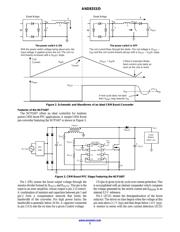
Basic Operation of a CRM Boost Converter
For medium power (< 300 W) applications, critical
conduction mode (CRM) is the preferred control method.
Critical conduction mode occurs at the boundary between
discontinuous conduction mode (DCM) and continuous
conduction mode (CCM). In CRM, the next driver on time
is initiated when the boost inductor current reaches zero.
Hence, CRM combines the lower peak currents of CCM
operation with the zero current switching of DCM
operation. This control method causes the frequency to vary
with the line input voltage and the output load. The operation
and waveforms of a PFC boost converter are illustrated in
Figure 2. For detailed information on the operation of
a CRM Boost Converter for PFC applications, please refer
to AND8123 at www.onsemi.com
.
APPLICATION NOTE
www.onsemi.com
Verzeichnis