
herunterladen
© Semiconductor Components Industries, LLC, 2010
February, 2010 − Rev. 2
1 Publication Order Number:
AND8393/D
AND8393/D
48 W, 24 V/7.5 V Universal
Input AC-DC Printer
Adapter Using the NCP1219
Prepared by: Dave Briggs
ON Semiconductor
Introduction
The NCP1219 is the newest part in the NCP12XX family
of current−mode flyback controllers. The controller features
dynamic self supply (DSS), eliminating the need for
external startup circuitry, contributing to a cost effective,
low parts count flyback controller design. The NCP1219
also includes a user programmable skip cycle threshold,
reducing power dissipation at light loads and in standby
mode. An externally provided latch signal delivered to the
Skip/latch pin allows the realization of protection
functionality.
The 48 W ac adapter demonstration board targets a printer
adapter application with a 24 V output, reconfigurable to
7.25 V in standby mode selectable with an external signal.
The use of DSS mode is demonstrated for low input
voltages, while an auxiliary winding is used for higher input
voltages to maintain standby power below 1 W. The
NCP1219 demonstration board shows latched−mode
protection function through the optional primary and
secondary overvoltage protection circuits.
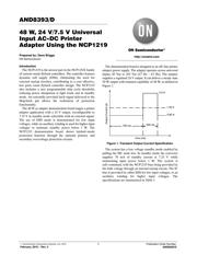
The demonstration board is designed as an off−line printer
adapter power supply. The adapter operates across universal
inputs, 85 Vac to 265 Vac (47 Hz – 63 Hz). The adapter
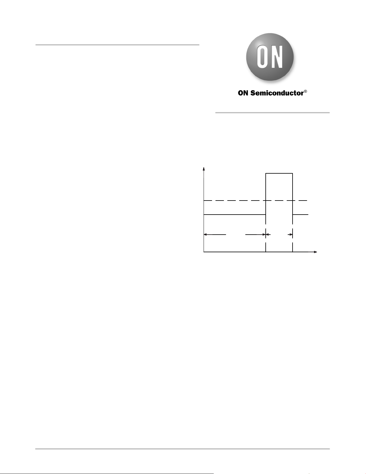
supplies a regulated 24 V output. It can deliver a steady state
30 W output with transient capability of 48 W, as defined in
Figure 1.
Figure 1. Transient Output Current Specification
time (ms)
Output Current (A)
0.92 A
2.0 A
1.25 A
700 ms
300 ms
The system has a low voltage standby mode enabled by
pulling the MC node low. In standby mode the converter
supplies 70 mA of standby current at 7.25 V while
maintaining input power below 1 W. The system is
self−contained, with the NCP1219 bias being provided by
the bulk voltage through an internal startup circuit. The IC
bias is provided by either DSS for low input voltages, or an
auxiliary winding for higher input voltages. The
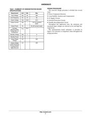
specifications are summarized in Table 1.
http://onsemi.com
Verzeichnis