


herunterladen
© Semiconductor Components Industries, LLC, 2015
February, 2015 - Rev. 0
1 Publication Order Number:
AND9204/D
AND9204/D
NCL30088 and NCL30085
Safety Test Considerations
Introduction
NCL30088 and NCL30085 are controllers targeting
isolated and non−isolated constant current LED drivers.
These highly integrated devices are optimized for an
efficient and accurate light control with a minimum number
of external components. Details on their operation can be
found at www.onsemi.com
. These devices also tend to ease
the manufacturing and compliance with safety
requirements. Elements of a LED driver can be accidentally
shorted, badly soldered or damaged as a result of
manufacturing or handling incidents, excessive operating
stress or other troubles. In particular, adjacent pins of
controllers can be shorted together or a pin can be grounded
or badly connected. It is common to expect that such
open/short situations do not cause fire, smoke nor loud
noise.
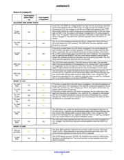
Testing Conditions
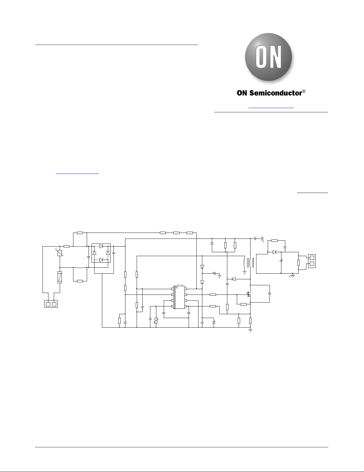
Safety tests have been performed in an open−frame,
wide−mains, 10 W, 500 mA LED driver at 25°C ambient
temperature. Figure 1 provides its application schematic.
The experiments have been made with NCL30088B
samples (auto−recovery protection mode and 250 mV
reference voltage).
SD
ZCD
VS
COMP
DRV
VCC
C7
22p
C4
10mF
R1
3
Q1
NDD03N80
D8
DBL105G
D3
MURS220
R2
24k
R3
8.2k
C3
470mF
R4
10
R8
33k
Vout: 12 − 20V
Iout: 500 mA
Line Voltage:
85 − 265 V rms
R5
47k
R6
2700k
D1
mur180
R9
470k
R10
470k
C6
4.7nF
C8
4.7n
R12
3
C10
1mF
R13
47k
R14
22
R16
33k
R18
NC
C12
100n
C13
1n
R15
2700k
R33
820
D2
BAV21
R
RV1
V275LA4P
0.5W
0.5W
1000V
35V
R20
22
C18
22p
RN1
NB12P00104JBB
1
.
.
.
T1
FLY_XFMR
3
4
6
9
12
C19
NC
LED+
LED−
C21
1n
Type = Y
F1
J1
J3
CS
GND
R29
33k
C5
47nF
Type = X2
C2
47pF
Vout
Vcs
Vds
L2
2.2mH
R7
5.6k
R11
4.7
C17
100nF
L3
2.2mH
R32
5.6k
35V
1
2
3
45
8
6
7
NCL30085
C1
NC
C9
47mF
D4
1N4148
NCL30088
Figure 1. Application Schematic
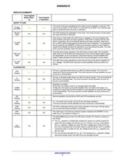
SHORT faults were made by means of a manual switch so
that SHORT conditions could be applied before and during
operation. Pin floating conditions were created by inserting
a socket between the board and the socket the circuit was
soldered to. The appropriate pin of the intermediate socket
was removed to test the floating fault under interest. The
manual switch gave the possibility to reconnect the
NCL30088 pin. Tests were made at 25°C ambient
temperature.
www.onsemi.com
APPLICATION NOTE
Verzeichnis