
herunterladen

© Semiconductor Components Industries, LLC, 2007
August, 2007 - Rev. 1
1 Publication Order Number:
AND8234/D
AND8234/D
NUD4001 Dimming Ability
Demonstration Board
Prepared by: Fionn Sheerin
ON Semiconductor
General Description
The NUD4001 produces a constant current to power
LEDs, using an external resistor to determine the current
level. This works well for applications which require a
constant brightness from the LEDs (on or off). In
applications which require the LED to dim, or to operate at
moderate intensities, a pulse width modulated signal can be
used to vary the intensity of the LED by switching it on and
off at high frequencies (greater than 100 Hz). This turns out
to be a very straightforward circuit, requiring few
components and giving a full dimming range from
completely off to completely on.
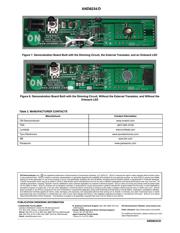
The NUD4001 dimming demonstration board
demonstrates this circuit. It can be built with an external
transistor to handle voltages up to 18 V (instead of 6 V), and
it can use either a single LED on the board or it can connect
to an external LED. It can also be built without the dimming
circuit, providing a constant output current without the
dimming ability.
Features:
• Adjustable LED brightness
• Constant LED current when LED is on
• Minimal external circuit requirements
NUD4001 Overview
The high current LED driver (NUD4001) uses an external
resistor to determine the output current. The resistor is
connected between the first and third pins of the device, and
the output current is:
I
out
+
0.7V
R
ext
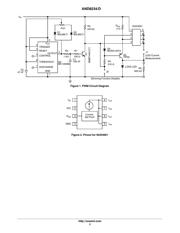
The LED driver also has an input voltage (Pin 1), and a
ground (Pin 4, see Figure 2). If the ground pin is
disconnected, then the device stops functioning. The circuit
used in the dimming demonstration board takes advantage
of this requirement to switch the device on and off.
The dimming demonstration board features an external
transistor in parallel with the NUD4001, which decreases
the power dissipated in the LED driver, allowing larger
currents and higher input voltages (see AND8197/D,
NUD4001 LED Driver Demonstration Boards).
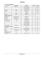
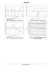
Basic Circuit Operation
The dimming demonstration board runs on 6 VDC
without the external transistor, or up to 18 VDC with the
external transistor (at 350 mA output current). This input
can be applied either to the test points labeled “VDC“, or
using a DC supply connected to the 2.1 mm power jack
(labeled “CON1”). The board has two possible LED
configurations, one with an LED, and one with a connector
to drive a load not on the demo board. If the connector is used
to drive an LED in parallel with the LED on the board, the
two LEDs must have the same voltage drop (or else they will
not share the current evenly), and the current limit resistor
on the LED driver needs to be adjusted to supply the proper
current to the parallel LEDs. When running, the
potentiometer can be used to adjust the duty cycle of the
timer circuit, which turns the LED drivers on and off; which
reduces the average current through the LEDs. The circuit
also contains one jumper, in series with the load, which may
be used to connect an ammeter in series with the load to
monitor the current regulation.
Power Consumption and Voltage Constraints
Ignoring power dissipation, the board can operate at any
voltage between 6 V and 18 V, provided the input voltage is
at least 1.4 V higher than the total V
f
of the LED load.
However, with this board design, the LED driver cannot
dissipate more than 1.1 W of power without the external
transistor. Using the external transistor, the drive current will
flow primarily through the external transistor, which has a
maximum power dissipation of 5.3 W (at an ambient
temperature of 25°C, with the heatsink on this particular
board). The power dissipated in the LED driver can be easily
calculated by subtracting the V
f
of the load from the input
voltage, to get the voltage across the driving circuit, and then
multiplying by the load current.
P + (V
in
* V
LED
) @ I
LED
For this board, the power must remain below 1.1 W
without the external transistor, and below 5.3 W with the
external transistor. If, for example, this board is built with
the external transistor, connected to one LED with a 2.9 V
V
f
, driving a current of 350 mA, then the circuit could
APPLICATION NOTE
http://onsemi.com
Verzeichnis