
herunterladen
Specifications which provide more details for the proper and safe use of the described product are available upon request.
All specifications are subject to change without notice.
Inductors
MLF Series MLF2012 Type
For General Applications
SMD
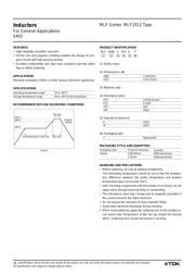
FEATURES
• High-reliability monolithic structure.
• Ferrite core and magnetic shielding enables the design of com-
pact circuits with high packing density.
• Excellent solderability and high heat resistance permits either
flow or reflow soldering.
APPLICATIONS
Personal computers, HDDs, or other various electronic appliances.
SPECIFICATIONS
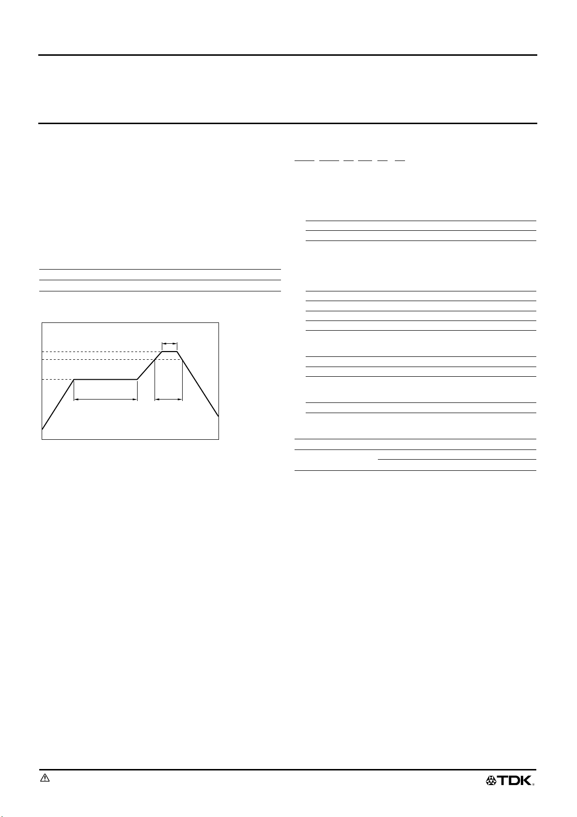
RECOMMENDED REFLOW SOLDERING CONDITIONS
PRODUCT IDENTIFICATION
(1) Series name
(2) Dimensions L
×
W
(3) Material code
(4) Inductance value
(5) Inductance tolerance
(6) Packaging style
PACKAGING STYLE AND QUANTITIES
HANDLING AND PRECAUTIONS
• Before soldering, be sure to preheat components.
The preheating temperature should be set so that the tempera-
ture difference between the solder temperature and product
temperature does not exceed 150°C.
• After mounting components onto the printed circuit board, do not
apply stress through board bending or mishandling.
• The inductance value may change due to magnetic saturation if
the current exceeds the rated maximum.
• Do not expose the inductors to stray magnetic fields.
• Avoid static electricity discharge during handling.
• When hand soldering, apply the soldering iron to the printed cir-
cuit board only. Temperature of the iron tip should not exceed
300°C. Soldering time should not exceed 3 seconds.
Operating temperature range –25 to +85°C
Storage temperature range –40 to +85°C[Unit of products]
10s max.
40s max.Preheating 60 to 120s min.
Natural
cooling
220°C
200°C
150°C
Time
(
s
)
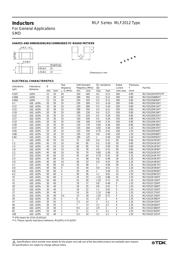
1608 1.6
×
0.8mm
2012 2.0
×
1.25mm
47N 47nH[0.047
µ
H]
R15 0.15
µ
H
1R0 1
µ
H
100 10
µ
H
K ±10%
M ±20%
T Taping [reel]
Packaging style Product’s thickness
Quantity
Taping 0.8/0.85mm 4000 pieces/reel
1.25mm
2000 pieces/reel
MLF 1608 A 1R0 K T
(1) (2) (3) (4) (5) (6)
Verzeichnis