
herunterladen

© 2005 Microchip Technology Inc. DS01016A-page 1
AN1016
INTRODUCTION
Target Audience
This application note is intended for hardware and
firmware design engineers that need to accurately
detect small capacitance values.
Goals
• Detect small capacitances (e.g., 0.5 pF to 6.5 nF)
• Use minimal number of external components
• Give simple firmware solution
• Highlight design tradeoffs and alternatives
Description
This application note shows how to use a PICmicro
®
microcontroller and minimal external circuitry to detect
small capacitances. The design is based on an opera-
tional amplifier (op amp) integrator. A capacitive
humidity sensor is used to illustrate this type of
application.
The design is measured to verify the theory and design
choices. Alternatives and modifications to this design
are briefly discussed.
References to documents that treat these subjects in
more depth and breadth have been included in the
“References” section.
The appendices give detailed information that supports
the text of this application note.
Related Demo Board
The measurements for this application note were made
on the Humidity Sensor PICtail™ Demo Board, which
is discussed in the user’s guide (DS51594) [15]. This
board is further described by:
• Order Number: PIC16F690DM-PCTLHS
• Assembly Number: 102-00084R1
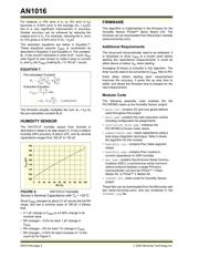
INTEGRATOR SOLUTION
This section describes a design that accurately
measures small capacitances. It uses dual slope
integration to measure the sensor’s capacitance. Using
an integrator for measuring small capacitive sensors
has three main advantages:
• Any sensor parasitic capacitance (i.e., case-to-
ground stray) is forced to the correct voltage by
the op amp.
• The parasitic capacitance in parallel is much
smaller than other methods.
• The measured waveform has a constant slope,
which improves the timing accuracy.
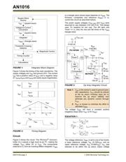
Block Diagram
Figure 1 shows the block diagram of the integrator
solution. The “Square Wave Source” voltage (V
INT
) is
converted to a square wave current (I
INT
). I
INT
is then
passed to an integrator comprised of an op amp and
the sensor capacitor (C
SEN
). The “Integrator” outputs a
voltage triangle wave (V
SEN
) whose slope depends on
C
SEN
. The “Threshold Crossing Detector” tells when
V
SEN
is above or below two reference voltages: a lower
voltage (V
RL
) and a higher voltage (V
RH
).
The “Magnitude Control” firmware routine changes the
polarity of V
INT
so that V
SEN
goes past both V
RL
and
V
RH
by the desired amount. The “Timing Count”
firmware routine counts the time elapsed for V
SEN
to go
from V
RL
to V
RH
(t
1
), and to go from V
RH
to V
RL
(t
2
).
The “Calculations” firmware routine calculates C
SEN
then the relative humidity (RH) from that capacitance.
Author: Kumen Blake and Steven Bible
Microchip Technology Inc.
Detecting Small Capacitive Sensors Using the MCP6291 and
PIC16F690 Devices
Verzeichnis
- ・ Blockdiagramm on Seite 1 Seite 2
- ・ Anwendungsbereich on Seite 11