
herunterladen
2000 Microchip Technology Inc. DS00682C-page 1
AN682
INTRODUCTION
Beyond the primitive transistor, the operational ampli-
fier is the most basic building block for analog applica-
tions. Fundamental functions such as gain, load
isolation, signal inversion, level shifting, adding and/or
subtracting signals are easily implemented with this
building block. More complex circuits can also be
implemented, such as the instrumentation amplifier, a
current to voltage converter, and filters, to name only a
few. Regardless of the level of complexity of the opera-
tional amplifier circuit, knowing the fundamental opera-
tion and behavior of this building block will save a
considerable amount of upfront design time.
Formal classes on this subject can be very comprehen-
sive and useful. However, many times they fall short in
terms of experience or common sense. For instance, a
common mistake that is made when designing with
operational amplifiers is to neglect to include the
bypass capacitors in the circuit. Operational amplifier
theory often overlooks this practical detail. If the bypass
capacitor is missing, the amplifier circuit could oscillate
at a frequency that “theoretically” doesn’t make sense.
If text book solutions are used, this is a difficult problem
to solve.
This application note is divided into three sections. The
first section will list fundamental amplifier applications
with the design equations included. These amplifier cir-
cuits where selected with embedded system integra-
tion in mind.
The second section will use these fundamental circuits
to build useful amplifier functions in embedded control
applications.
The third section will identify the most common single
supply operational amplifier (op amp) circuit design
mistakes. This list of mistakes has been gathered over
many years of trouble shooting circuits with numerous
designers in the industry. The most common design pit-
falls can easily be avoided if the check list from this
short tutorial is used.
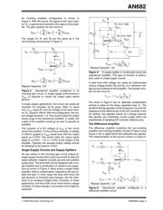
FUNDAMENTAL OPERATIONAL
AMPLIFIER CIRCUITS
The op amp is the analog building block that is analogous
to the digital gate. By using the op amp in the design, cir-
cuits can be configured to modify the signal in the same
fundamental way that the inverter, AND, and OR gates
do in digital circuits. In this section, fundamental building
blocks such as the voltage follower, non-inverting gain
and inverting gain circuits will be discussed. This will be
followed by a rail splitter, difference amplifier, summing
amplifier and current to voltage converter.
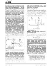
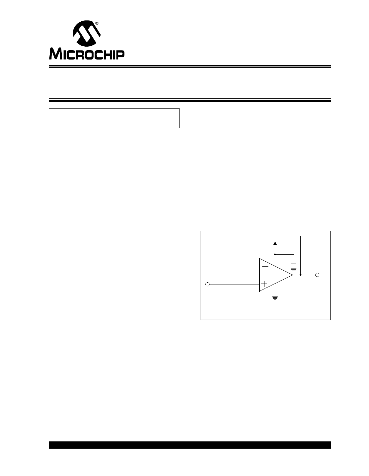
Voltage Follower Amplifier
Starting with the most basic op amp circuit, the buffer
amplifier (shown in Figure 1) is used to drive heavy
loads, solve impedance matching problems, or isolate
high power circuits from sensitive, precise circuitry.
Figure 1: Buffer Amplifier; also called a voltage
follower.
The buffer amplifier, shown in Figure 1, can be imple-
mented with any single supply, unity gain stable ampli-
fier. In this circuit as with all amplifier circuits, the op
amp must be bypassed with a capacitor. For single sup-
ply amplifiers that operate in bandwidths from DC to
megahertz, a 1µF capacitor is usually appropriate.
Sometimes a smaller bypass capacitor is required for
amplifiers that have bandwidths up to the 10s of mega-
hertz. In these cases a 0.1µF capacitor would be appro-
priate. If the op amp does not have a bypass capacitor
or the wrong value is selected, it may oscillate.
The analog gain of the circuit in Figure 1 is +1 V/V.
Notice that this circuit has a positive overall gain but the
feedback loop is tied from the output of the amplifier to
Author: Bonnie Baker
Microchip Technology Inc.
MCP601
V
OUT
= V
IN
*
*Bypass Capacitor, 1µF
V
DD
2
7
3
4
6
V
OUT
V
IN
Using Single Supply Operational Amplifiers
in Embedded Systems
Verzeichnis
- ・ Technische Daten on Seite 8
- ・ Anwendungsbereich on Seite 8