

herunterladen

2003 Microchip Technology Inc. DS00872A-page 1
M
AN872
INTRODUCTION
The MCP2510 stand-alone CAN controller was
originally developed to give CAN system and module
designers more flexibility in their design by allowing
them to choose the best processor for their application.
By using the MCP2510, designers were not restricted
to using processors with integrated CAN controllers.
Today, the CAN market continues to grow and
proliferate into other markets and different applications
and, both increasingly complex nodes and simpler
nodes are being developed to further distribute control
among the CAN network. The complex nodes may
require using a 32-bit MCU, ASIC, CPLD, DSP or some
other device that does not have an on-board CAN
controller. The simple nodes may only require small
program space and not need all of the extra peripherals
found on many of the MCUs with integrated CAN.
The MCP2515 addresses these new market needs,
and is designed to be pin and functionally compatible to
the MCP2510. All known MCP2510 errata have been
addressed in the MCP2515. Additionally, there are
several enhancements with the MCP2515, designed
for increased performance.
While the MCP2515 was designed to be functionally
compatible to the MCP2510, there are some
differences between the two devices due to both the
MCP2510 errata being fixed and the enhanced
features of the MCP2515. These differences should be
invisible in most applications that choose to upgrade to
the MCP2515. This application note discusses the
differences between the MCP2510 and MCP2515 (and
the possible impact of these differences) in an effort to
assist with the upgrade process.
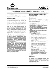
MCP2515 ENHANCEMENTS AND
DIFFERENCES
Enhancements
The enhancements in the MCP2515 are designed as a
super-set to the basic functionality of the MCP2510.
These enhancements include:
• 40 MHz operation
• 10 MHz Serial Peripheral Interface™ (SPI™)
• Data byte filtering on the first 16 bits in the data
field (standard 11-bit frames only)
• One-shot mode to automatically abort messages
that lose arbitration or are interrupted by an error
frame
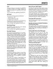
• Start-of-Frame (SOF) output pin used to detect
valid start-of-frames
• Three new SPI instructions:
- Read RX Buffer Command
Eliminates the eight bit address required by a
normal read command.
Eight bit instruction that sets the address
pointer to one of four addresses depending
on two bits. Points to the “ID” or “data” of the
two receive buffers.
- RX Status Command
Used to quickly read important information
about a received message.
Eight bit instruction followed by the status of
received message: Standard/Extended,
Frame Type (data frame/remote) and filter
match.
- Load TX Buffer Command
Eliminates the eight bit address required by a
normal write command.
Eight bit instruction that sets the address
pointer to one of six addresses to quickly
write to a transmit buffer. Points to the “ID” or
“data” address of any of the three transmit
buffers.
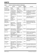
Differences
A summary of the differences (including the
enhancements and other changes) is shown in Table 1.
The sections following the table decribe each
difference in greater detail.
Author: Pat Richards
Microchip Technology Inc.
Upgrading from the MCP2510 to the MCP2515