

herunterladen
Freescale Semiconductor
Data Sheet: Technical Data
Document Number: IMX53IEC
Rev. 7, 05/2015
MCIMX53xC
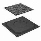
Package Information
Plastic Package
Case TEPBGA-2 19 x 19 mm, 0.8 mm pitch
Ordering Information
See Table 1 on page 2
© 2011-2015 Freescale Semiconductor, Inc. All rights reserved.
1 Introduction
The i.MX53 processor features ARM Cortex™-A8
core, which operates at clock speeds as high as
800 MHz. It provides DDR2/LVDDR2-800,
LPDDR2-800, or DDR3-800 DRAM memories.
The flexibility of the i.MX53 architecture allows for its
use in a wide variety of applications. As the heart of the
application chipset, the i.MX53 processor provides all
the interfaces for connecting peripherals, such as
WLAN, Bluetooth™, GPS, hard drive, camera sensors,
and dual displays.
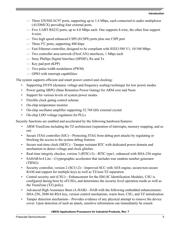
Features of the i.MX53 processor include the following:
• Applications processor—The i.MX53xD
processors boost the capabilities of high-tier
portable applications by satisfying the ever
increasing MIPS needs of operating systems and
games. Freescale’s Dynamic Voltage and
Frequency Scaling (DVFS) provides significant
power reduction, allowing the device to run at
lower voltage and frequency with sufficient
MIPS for tasks such as audio decode.
i.MX53 Applications
Processors for Industrial
Products
Silicon Version 2.1
1. Introduction . . . . . . . . . . . . . . . . . . . . . . . . . . . . . . . . . . . 1
1.1. Functional Part Differences and Ordering
Information . . . . . . . . . . . . . . . . . . . . . . . . . . . . . . . 2
1.2. Features . . . . . . . . . . . . . . . . . . . . . . . . . . . . . . . . . 3
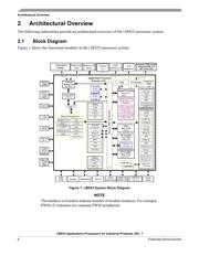
2. Architectural Overview . . . . . . . . . . . . . . . . . . . . . . . . . . . 6
2.1. Block Diagram . . . . . . . . . . . . . . . . . . . . . . . . . . . . 6
3. Modules List . . . . . . . . . . . . . . . . . . . . . . . . . . . . . . . . . . . 7
3.1. Special Signal Considerations . . . . . . . . . . . . . . . 16
4. Electrical Characteristics . . . . . . . . . . . . . . . . . . . . . . . . 16
4.1. Chip-Level Conditions . . . . . . . . . . . . . . . . . . . . . 16
4.2. Power Supply Requirements and Restrictions . . . 23
4.3. I/O DC Parameters . . . . . . . . . . . . . . . . . . . . . . . . 26
4.4. Output Buffer Impedance Characteristics . . . . . . 32
4.5. I/O AC Parameters . . . . . . . . . . . . . . . . . . . . . . . . 36
4.6. System Modules Timing . . . . . . . . . . . . . . . . . . . . 43
4.7. External Peripheral Interfaces Parameters . . . . . 65
4.8. XTAL Electrical Specifications . . . . . . . . . . . . . . 141
5. Boot Mode Configuration . . . . . . . . . . . . . . . . . . . . . . . 142
5.1. Boot Mode Configuration Pins . . . . . . . . . . . . . . 142
5.2. Boot Devices Interfaces Allocation . . . . . . . . . . . 143
5.3. Power Setup During Boot . . . . . . . . . . . . . . . . . . 144
6. Package Information and Contact Assignments . . . . . 145
6.1. 19x19 mm Package Information . . . . . . . . . . . . . 145
7. Revision History . . . . . . . . . . . . . . . . . . . . . . . . . . . . . . 170
Verzeichnis
- ・ Abmessungen des Paketumrisses on Seite 16 Seite 26 Seite 145 Seite 146 Seite 147
- ・ Teilenummerierungssystem on Seite 2
- ・ Blockdiagramm on Seite 6
- ・ Beschreibung der Funktionen on Seite 3 Seite 6 Seite 7 Seite 8 Seite 9
- ・ Technische Daten on Seite 16 Seite 17 Seite 78 Seite 94 Seite 95
- ・ Anwendungsbereich on Seite 2 Seite 3 Seite 4 Seite 5 Seite 6
- ・ Elektrische Spezifikation on Seite 16 Seite 17 Seite 18 Seite 19 Seite 20
- ・ Teilenummernliste on Seite 16