
herunterladen
© Semiconductor Components Industries, LLC, 2014
August, 2014 − Rev. 14
1 Publication Order Number:
MC74HC14A/D
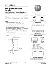
MC74HC14A
Hex Schmitt-Trigger
Inverter
High−Performance Silicon−Gate CMOS
The MC74HC14A is identical in pinout to the LS14, LS04 and the
HC04. The device inputs are compatible with Standard CMOS
outputs; with pullup resistors, they are compatible with LSTTL
outputs.
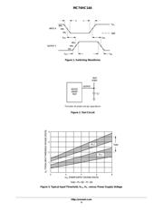
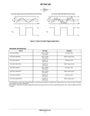
The HC14A is useful to “square up” slow input rise and fall times.
Due to hysteresis voltage of the Schmitt trigger, the HC14A finds
applications in noisy environments.
Features
• Output Drive Capability: 10 LSTTL Loads
• Outputs Directly Interface to CMOS, NMOS and TTL
• Operating Voltage Range: 2.0 to 6.0 V
• Low Input Current: 1.0 mA
• High Noise Immunity Characteristic of CMOS Devices
• In Compliance With the JEDEC Standard No. 7.0 A Requirements
• Chip Complexity: 60 FETs or 15 Equivalent Gates
• NLV Prefix for Automotive and Other Applications Requiring
Unique Site and Control Change Requirements; AEC−Q100
Qualified and PPAP Capable
• These Devices are Pb−Free, Halogen Free/BFR Free and are RoHS
Compliant
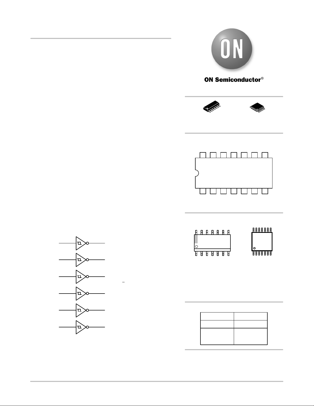
LOGIC DIAGRAM
Y1A1
A2
A3
A4
A5
A6
Y2
Y3
Y4
Y5
Y6
1
3
5
9
11
13
2
4
6
8
10
12
Y = A
Pin 14 = V
CC
Pin 7 = GND
http://onsemi.com
See detailed ordering and shipping information in the package
dimensions section on page 5 of this data sheet.
ORDERING INFORMATION
MARKING DIAGRAMS
A = Assembly Location
L, WL = Wafer Lot
Y, YY = Year
W, WW = Work Week
G or G = Pb−Free Package
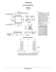
TSSOP−14
DT SUFFIX
CASE 948G
SOIC−14 NB
D SUFFIX
CASE 751A
HC14AG
AWLYWW
1
14
HC
14A
ALYWG
G
1
14
(Note: Microdot may be in either location)
TSSOP−14
SOIC−14 NB
PIN ASSIGNMENT
1314 12 11 10 9 8
21 34567
V
CC
A6 Y6 A5 Y5 A4 Y4
A1 Y1 A2 Y2 A3 Y3 GND
14−Lead (Top View)
L
H
FUNCTION TABLE
Inputs Outputs
A
H
L
Y
Verzeichnis
- ・ Konfiguration des Pinbelegungsdiagramms on Seite 1
- ・ Abmessungen des Paketumrisses on Seite 6 Seite 7
- ・ Paket-Footprint-Pad-Layout on Seite 6 Seite 7
- ・ Teilenummerierungssystem on Seite 1 Seite 5 Seite 7
- ・ Markierungsinformationen on Seite 1 Seite 7
- ・ Typisches Anwendungsschaltbild on Seite 1
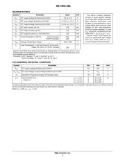
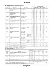
- ・ Technische Daten on Seite 5
- ・ Anwendungsbereich on Seite 1 Seite 5
- ・ Teilenummernliste on Seite 2