
herunterladen
Maxim > Design Support > Technical Documents > Application Notes > A/D and D/A Conversion/Sampling Circuits > APP 5074
Maxim > Design Support > Technical Documents > Application Notes > Microcontrollers > APP 5074
Keywords: adc, dac, analog to digital, digital to analog, microcontroller, op amp, uC
APPLICATION NOTE 5074
Implementing an ADC with a Microcontroller, an
Op Amp, and Resistors
By: Gordon Lee
May 11, 2012
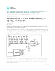
Abstract: This design idea explains how to implement an 8-bit analog-to-digital converter (ADC), using a
microcontroller and some common components.
Analog-to-digital converters (ADCs) are used in a wide range of electronic devices. However, most of the
low-cost microcontrollers do not include an ADC peripheral. This design idea provides a way to implement
an 8-bit ADC using a microcontroller and some common components. The circuit consists of resistors and
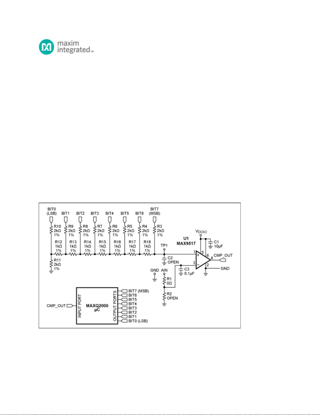
an operational amplifier (Figure 1).
Figure 1. ADC circuitry.
The R3–R18 resistors form an R/2R resistor ladder network, which converts the digital information into an
analog output. In other words, it is a simple DAC. Bit7 (MSB) (the most significant bit) to Bit0 (LSB) (the
least significant bit) are driven from the digital output ports of the microcontroller. The equation for the
output voltage of the DAC is:
Page 1 of 3