
herunterladen

Maxim > Design Support > Technical Documents > Application Notes > Automotive > APP 3806
Maxim > Design Support > Technical Documents > Application Notes > Basestations/Wireless Infrastructure > APP 3806
Maxim > Design Support > Technical Documents > Application Notes > High-Speed Interconnect > APP 3806
Keywords: LVDS transceiver, Point-to-Point link, Serializer, Deserializer, Digital Video Link, LCD display,
Camera sensing, Automotive navigation, video surveillance, Bit error rate, eye diagram, LVDS SerDes
APPLICATION NOTE 3806
Performance Test for a Serializer and Deserializer
Pair: MAX9247 and MAX9218
May 26, 2006
Abstract: High-speed serialized data connection has been widely used in video displays, digital camera
sensing, and backplane data transmission in networks, servers, and 3G base stations. Maxim developed
products for serial link transmitters and receivers. This application note demonstrates the performance of
a typical serializer and deserializer (SerDes) pair (the MAX9247 and MAX9218) under various cable
type, cable length, and data rate conditions. The resulting information is a good guide for applications
that require high-speed, serialized data connection.
Introduction
Maxim's high-speed serializer and deserializer (SerDes) products have been used in automotive,
networking, server, and 3G base stations for video, image, and data transmissions. The MAX9247
serializer and the MAX9218 deserializer form a typical pair of a single LVDS link with embedded clock.
The highest serial-link data rate, which the pair can reach, is up to 800Mbps.
This application note demonstrates the performance of this data transceiver link based on different cable
types, cable lengths, and data rates. The article also shows the performance improvements that result
from Maxim's proprietary pre-emphasis function and line equalizer. To meet the harsh environment in an
automotive application, this SerDes pair is also tested in the -40°C to +105°C temperature range.
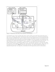
Test Setup
The test setup consists of an Agilent ParBERT 81250 tester, TDS784C 1GHz digital scope, TEK P6247
Differential probe, and the MAX9217/MAX9218 EV kit board. The Agilent 81250 is a parallel bit error rate
tester (BERT). The components are connected as shown in the following illustration (Figure 1).
Page 1 of 8