
herunterladen

Maxim > Design Support > Technical Documents > Application Notes > Automotive > APP 4099
Maxim > Design Support > Technical Documents > Application Notes > High-Speed Interconnect > APP 4099
Keywords: SerDes, LVDS, Eye Template, Eye Diagram, Serializer, Deserializer, Link performance, Link
Margin, Deterministic Jitter, Sinusoid Jitter, Random Jitter, Bit Error Rate, Differential Link
APPLICATION NOTE 4099
Evaluate Serializer-Deserializer (SerDes)
Performance by Creating Eye Pattern Templates
Jul 22, 2008
Abstract: Maxim has developed a family of serializer and deserializer products for high-speed, serial data
interconnection in video display and digital image sensing. Today's designers are very interested in the
performance measurement and margin of a serial data link established by a serializer and deserializer
(SerDes) chipset. This application note presents an experimental approach first to measure the eye
template of a serial link, then to use that measurement to derive the link performance margin.
Introduction
Maxim's high-speed LVDS serializer and deserializer (SerDes) products have been used in the automotive
and telecom industries for video display, image sensing, and data transmissions. When using a SerDes
chipset for high-speed data interconnection, the users expect to know the performance of the SerDes link
and the margin for reliable data transmission. Designers typically use an eye diagram and an eye template
to describe the performance and margin of a serial link.
1,2
There is, however, no clear and convincing
methodology for determining the eye template based on experimental data.
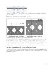
This application note presents a systematic approach to determine an eye template from the measured eye
diagrams and bit-error rates of the serial link. To illustrate the process, eye templates and link margins for
the MAX9217 and MAX9250 SerDes chipset were generated. The system temperatures for the tests were
+25°C, +95°C and +105°C, and cables of various lengths were used.
Note: the results obtained from the MAX9250 in this test system also apply to the MAX9248 deserializer.
Except for spread-spectrum parallel outputs, the MAX9248 is the same receiving circuit as the MAX9250.
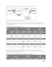
Test Setup
The test setup consists of the following instruments:
Agilent 86130A Bit Analyzer
Agilent 83752A Synthesizer Sweeper
Agilent 70820A Microwave Transition Analyzer
Agilent 3325A Function Generator
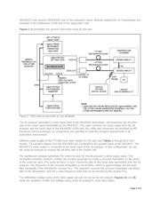
The physical link between the MAX9217 serializer and the MAX9250 deserializer is established through a
shielded high-quality cable (Part Number: PT1482) provided by MD Elektronik GmbH,
3
which connects two
Rosenberger
4
receptacles (Part Number: D4S20D-40ML5-Y, waterblue) mounted on the transmitter
Page 1 of 8