
herunterladen

Click here for an overview of the wireless
components used in a typical radio
transceiver.
Maxim > Design Support > Technical Documents > Tutorials > A/D and D/A Conversion/Sampling Circuits > APP 4300
Maxim > Design Support > Technical Documents > Tutorials > General Engineering Topics > APP 4300
Maxim > Design Support > Technical Documents > Tutorials > Measurement Circuits > APP 4300
Keywords: voltage references, voltage reference, DAC reference, three terminal reference, reference accuracy,
DAC, digital to analog converter, DAC design examples, error budget
TUTORIAL 4300
Calculating the Error Budget in Precision Digital-to-
Analog Converter (DAC) Applications
By: David Fry, Strategic Applications Engineering Manager
Sep 25, 2008
Abstract: This application note analyses the parameters that affect the errors in precision digital-to-analog
converter (DAC) applications. The analysis focuses on the factors introduced by both the data converter and
the voltage reference. It describes the calculations required to select the data converter and the reference to
meet the system's target specifications. The calculations are available in a spreadsheet.
Download associated spreadsheet.
Overview
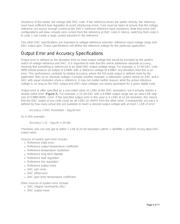
When designing a digital-to-analog converter (DAC) system, the DAC
specifications and its voltage reference work in tandem to produce the
overall system performance. Consequently, selection of both DAC and
reference should be made together. The components' specifications can
be traded off against each other to ensure that system specifications are
met at the lowest cost.
This application note focuses on Maxim's 3-terminal voltage references and precision DACs. To design a
system, one must first understand how the parts are specified and then how their performance characteristics
interact. Voltage references and DACs have many specifications. Only those factors relevant to the error
budget will be discussed here.
Voltage Reference Specifications
Initial Accuracy
This is the output voltage tolerance, ignoring any effects of temperature, input voltage, and load. Temperature
is normally +25°C.
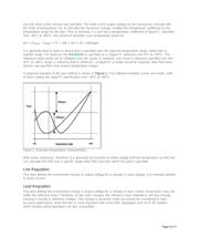
Output-Voltage Temperature Coefficient
This is the change in reference output voltage, measured for a given change in temperature and specified in
ppm/°C. Maxim uses the box method. The shape of the change vs. temperature characteristic is not specified;
Page 1 of 17
Verzeichnis