
herunterladen

Maxim > Design Support > Technical Documents > Application Notes > Protection and Isolation > APP 4483
Maxim > Design Support > Technical Documents > Application Notes > Sensors > APP 4483
Maxim > Design Support > Technical Documents > Application Notes > Signal Generation Circuits > APP 4483
Keywords: pulse-width modulation, PWM, 4-20mA transmitter, galvanic isolation, Schmitt-trigger buffer
APPLICATION NOTE 4483
PWM-Controlled 4–20mA Transmitter Is Galvanically
Isolated
Aug 05, 2010
Abstract:
This loop
-powered, 4–20mA precision transmitter includes a precision PWM signal coupler with
galvanic isolation from the PWM signal source. The external PWM-encoded signal is a rectangular waveform
generated by a microcontroller or PWM modulator, and is usually produced by a control algorithm run by the
microcontroller from a sensor output or other analog-command level.
A similar version of this article appeared in the February 24, 2009 issue of EE Times magazine.
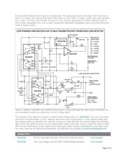
The accuracy of a 4–20mA transmitter depends on the integrity of its current-loop path, which must be free of
shunt paths and ground loops—both within the transmitter and external to it. External to the transmitter are
spurious paths in the outside loop wiring and its power supply. Internal to the transmitter, shunt paths and
ground loops are usually created at the point where you insert a control signal into the transmitter circuitry. To
eliminate errors introduced by possible spurious current paths, the signal must be DC coupled with full
galvanic isolation yet inserted with accuracy.
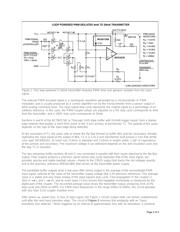
The circuit of Figure 1 comprises a loop-powered 4–20mA precision transmitter (MAX4236, BSP149, and
MAX6138A) with large-compliance output stage, and a precision PWM signal coupler with galvanic isolation
from the PWM signal source.
Page 1 of 4