


herunterladen

Keywords:
delta-sigma ADC, analog front end, industrial process control, PLC, industrial automation
APPLICATION NOTE 6184
USING THE MAX11254EVKIT AS A BUILDING
BLOCK PLATFORM FOR INDUSTRIAL
APPLICATIONS
By:
Yuriy Kurtsevoy, Sr. Strategic Applications Engineer
Carmelo Morello, Sr. Business Manager
Whitney Scott, Strategic Applications Engineer
Abstract: This application note aims to help evaluate the MAX11254/MAX11253 using the
MAX11254EVKIT configuration of different analog front ends to achieve higher performance for industrial
applications.
Introduction
When companies release a new part to the market, the aim is to offer a better solution for today’s
challenges that is not yet available, or to replace the existing solution with one that is more integrated,
and efficient. On the other hand, there is no single solution for the variety of applications and specific
requirements that consumers and companies have. This is especially true for industrial process control
and automation.
Maxim built an evaluation platform to explore different approaches and evaluate the performance of
MAX11254
/MAX11253, 6-channel, 24-/16-bit, low-noise, low-power, delta-sigma ADC that can be
suitable for different applications when we define and design the
MAX11254EVKIT board.
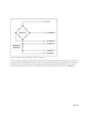
Front-End Implementations
There are three different front ends implemented in the MAX11254EVKIT:
1. Each channel is available with direct inputs from terminal blocks (J1-J3, J25, and J26). Each
channel can be configured with direct input or through the internal programmable gain amplifier
(PGA) with the gain options from 1 to 128 selectable in the graphical user interface (GUI). Inputs to
ADC channels are selected through J4 to J7 headers.
2. Channel 2 and 3 have an additional signal conditioning circuit built on the low-noise discrete
amplifiers, MAX9632, (U11, U12, U13, and U14 for channel 2, and U15, U16, U17, and U18 for
channel 3). These amplifiers can be configured either as a) single-ended inverting or non-inverting
front-end, or b) differential front-end through the jumper selection of J31 to J36 for the channel 2,
and through the jumper selection of J39 to J44 for the channel 3. Refer to the attached
MAX11254EVKIT schematic. In addition, the ADC inputs can be biased by V /2 by placing shunts
on J37, J38, J45 or J46.
REF
Page 1 of 6