

herunterladen
Maxim > Design Support > Technical Documents > Application Notes > Analog Switches and Multiplexers > APP 2854
Maxim > Design Support > Technical Documents > Application Notes > Circuit Protection > APP 2854
Keywords: fault protection, overvoltage protection, muxes, analog switches, spst, analog switch,
multiplexer, overvoltage
APPLICATION NOTE 2854
Low-Voltage Fault Protection
Nov 17, 2003
Abstract: This application note discusses the need for overvoltage protection in switches and muxes that
connect to the rest of the system. The MAX4711/MAX4712/MAX4713 analog switches operate from 2.7V
to 11V with integrated fault protection. Other methods of fault protection are discussed, along with their
advantages and disadvantages.
The standard supply voltages for today's systems (unipolar 3.3V or 5V, or bipolar ±3.3V or ±5V) are
usually the highest voltages available on a board. The board's input terminals may be exposed to
voltages higher than the supply voltages. When power to the board is off, voltages may remain at the
input terminals. The first element to be affected by overvoltage is often a multiplexer or a switch, so they
must protect downstream circuitry.
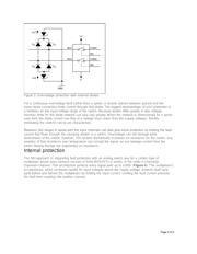
The pass element in an analog switch contains one or more MOSFETs and has parasitic clamping
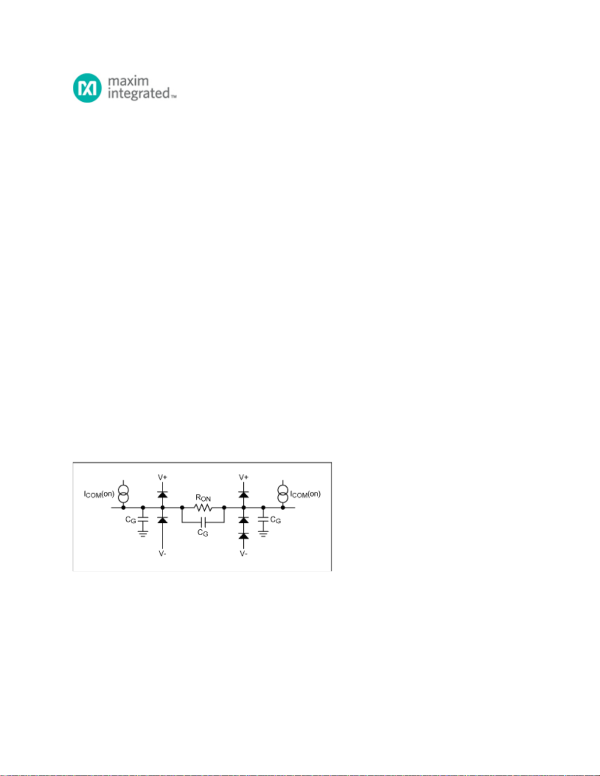
diodes to the supply voltages for ESD protection. Figure 1 shows the equivalent circuit diagram for a
closed analog switch. As long as V+ and V- are present and no input voltage exceeds those rails by the
forward bias voltage of the clamping diodes (typically 0.6V), the diodes are reverse-biased and no
current flows through them.
Figure 1. Equivalent circuit diagram for a closed switch.
Because improper supply-voltage sequencing can cause an overvoltage fault, many switches require that
the most positive voltage be applied first and the most negative last. An input voltage with supplies off or
an input voltage that exceeds a supply voltage causes current to flow through the clamping diodes.
Those diodes can handle only a couple of milliwatts (depending on the IC's semiconductor process)
before heat due to power dissipation damages the switch permanently.
Lower current levels can cause latchup-a condition in which the switch malfunctions and draws
Page 1 of 8
Verzeichnis
- ・ Blockdiagramm on Seite 5
- ・ Anwendungsbereich on Seite 6