
herunterladen

Maxim > Design Support > Technical Documents > Application Notes > Interface Circuits > APP 1076
Keywords: RS-485, rs484, EIA/TIA-485, fail-safe, variable-reluctance sensor, low-speed, medium speed,
ESD protected, rs485 transceiver
APPLICATION NOTE 1076
Fail-Safe, Low-Speed, Variable-Reluctance
Sensors
By: Phill Leyva
May 24, 2002
Abstract: Technical brief describes construction of a variable-reluctance sensor for detecting low- or
medium-speed events. A simple circuit is shown utilizing two channels of an ESD-protected RS-485
transceiver to deliver differential output data capable of providing fail-safe signals indicating sensor or
cable malfunction.
Variable-reluctance (VR) sensors are preferred for industrial and automotive environments because they
withstand mechanical vibration and high-temperature operation up to 300°C. In most applications, they
sense a steel target that is part of a rotating assembly. Because the unprocessed signal amplitude is
proportional to target speed, a sensor whose signal-processing circuitry is designed for high speed will
cease to function as rotation slows.
Hall-effect sensors are preferred for lower speeds (several pulses per second), but they require that a
magnet be attached to the rotating assembly, making them prone to failure when the magnet is broken
or damaged. Neither type (VR or Hall-effect) offers fail-safe detection of the processed signal in the
event of failure in the cable or sensor.
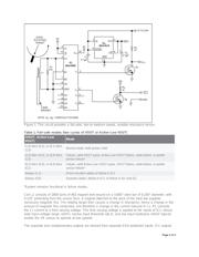
The circuit of Figure 1 is a fail-safe VR sensor suitable for low- to medium-speed operation. Comprising
of L1, R1, and a quad RS-422/RS-485 receiver (IC1), it provides the complementary, independent
output signals VOUT and Acitive-Low VOUT. Table 1 lists the resulting fail-safe modes. Supply voltage
can be +10V, +12V, or the control system's +24V DC source.
Page 1 of 4