Web Analytics
Datasheet
Teiledatenblatt > Battery Management IC > Maxim Integrated > MAX1898EUB42+ Datenblatt-PDF > MAX1898EUB42+ Anwendungshinweis Seite 1/5
MAX1898EUB42+
€ 2.71
Preis von AiPCBA

MAX1898EUB42+ Anwendungshinweis - Maxim Integrated

  • Hersteller:
    Maxim Integrated
  • Kategorie:
    Battery Management IC
  • Fallpaket
    uMAX-10
  • Beschreibung:
    Battery Charger Li-Ion/Li-Pol Packs 1400mA 4.2V 10Pin uMAX
Aktualisierte Uhrzeit: 2024-08-08 06:48:02 (UTC+8)

MAX1898EUB42+ Anwendungshinweis

Seite:von 5
PDF herunterladen
Neu laden
herunterladen
Maxim > Design Support > Technical Documents > Application Notes > Battery Management > APP 967
Maxim > Design Support > Technical Documents > Application Notes > Power-Supply Circuits > APP 967
Keywords: Lithium ion battery, Li+, battery charger, battery management, DC/DC, DC-DC converter,
linear charger, controlling power dissipation
APPLICATION NOTE 967
How to Minimize Power Dissipation in Li+ Linear
Chargers
Feb 21, 2002
Abstract: Techniques are described for minimizing power dissipation in linear battery chargers. Beginning
with a stable wall-cube switching power source, methods are described to limit the dissipation in the
linear charging circuit. Circuits are provided, calculations are shown, heat sinking for the PMOS pass
transistor is discussed, and suitable pass transistors are suggested.
Introduction
Data sheets for single-cell Li+ linear chargers seldom discuss power dissipation or how to deal with heat
dissipation. High input voltage and charge current increase the amount of power the pass element must
handle. This application note discusses how to maximize charging current while maintaining safe device
and system temperature limits.
Use a Proper DC Input Source
A low voltage input reduces the power dissipation. In order to charge the single-cell Li+ battery, we need
a well regulated 4.2V±1% or 4.1V±1% (depending on battery chemistry) output. The input voltage needs
to be higher to cover the voltage drops between the battery positive terminal and the input DC source.
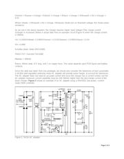
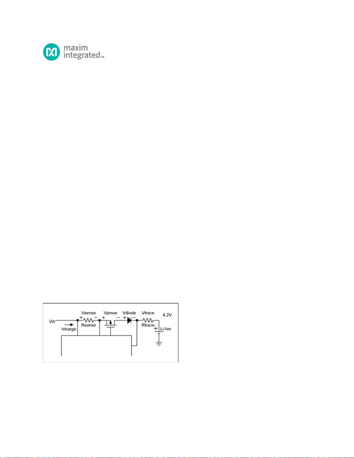
Figure 1 shows these for a typical charger.
Figure 1. Voltage drop contribution.
Vin = Vsense + Vpmos + Vtrace + Vdiode + 4.2V
The minimum input can be described as below.
Page 1 of 5

MAX1898EUB42+ Datenblatt-PDF

MAX1898EUB42+ Datenblatt PDF
Maxim Integrated
12 Seiten, 211 KB
MAX1898EUB42+ Anderes Datenblatt
Maxim Integrated
1 Seiten, 92 KB
MAX1898EUB42+ Anwendungshinweis
Maxim Integrated
5 Seiten, 109 KB

MAX1898 Datenblatt-PDF

MAX1898
Datenblatt PDF
Maxim Integrated
Linear Charger for Single-Cell Li Battery
MAX1898EUB42+T
Datenblatt PDF
Maxim Integrated
Battery Charger Li-Ion/Li-Pol Packs 1400mA 4.2V 10Pin uMAX T/R
MAX1898EUB41+T
Datenblatt PDF
Maxim Integrated
Battery Charger Li-Ion/Li-Pol Packs 1400mA 4.1V 10Pin uMAX T/R
MAX1898EUB42
Datenblatt PDF
Maxim Integrated
Battery Management Linear Charger for 1-Cell Li+ Battery
MAX1898EUB42+
Datenblatt PDF
Maxim Integrated
Battery Charger Li-Ion/Li-Pol Packs 1400mA 4.2V 10Pin uMAX
MAX1898EUB41+
Datenblatt PDF
Maxim Integrated
Battery Management Linear Charger for 1-Cell Li+ Battery
MAX1898EUB42-T
Datenblatt PDF
Maxim Integrated
Battery Charger Li-Ion/Li-Pol Packs 1400mA 4.2V 10Pin uMAX T/R
MAX1898EUB41
Datenblatt PDF
Maxim Integrated
Battery Management Linear Charger for 1-Cell Li+ Battery
MAX1898EUB41-T
Datenblatt PDF
Maxim Integrated
Battery Charger Li-Ion/Li-Pol Packs 1400mA 4.1V 10Pin uMAX T/R
MAX1898EVKIT
Datenblatt PDF
Maxim Integrated
Eval Kit MAX1898 (Linear Charger for Single-Cell Li+ Battery)
Datenblatt-PDF-Suche
Suche
100 Millionen Datenblatt-PDF, aktualisieren Sie mehr als 5.000 PDF-Dateien pro Tag.
Kontakt online
Bonnie - AiPCBA Sales Manager Online, vor 5 Minuten
Ihre E-Mail *
Nachricht *
Senden