
herunterladen
Maxim > Design Support > Technical Documents > Application Notes > Temperature Sensors and Thermal Management > APP 3641
Keywords: temperature,temperature sensor,thermal diode,remote diode
APPLICATION NOTE 3641
Migrating to the MAX6642 from Other Thermal Diode
Temperature Sensors
By: Kerry Lacanette
Nov 04, 2005
Abstract: The MAX6642 is a high-performance, low-cost, remote/local temperature sensor. When using the
MAX6642 to replace an older temperature sensor, such as the MAX1617 or the MAX6657, the following
guidelines should aid in the transition.
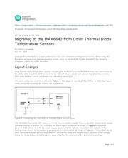
Layout Changes
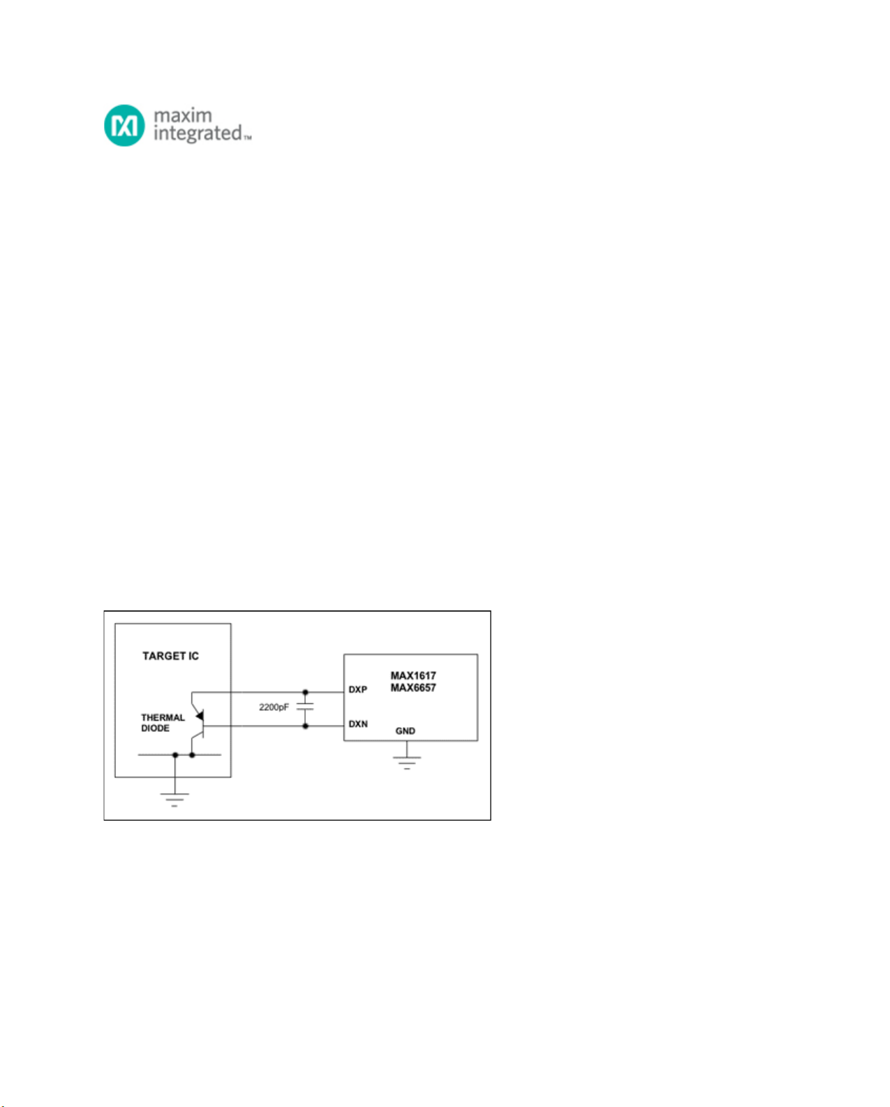
Most thermal diode temperature sensors, including the MAX1617 and the MAX6654, have two connections to
the diode: DXP and DXN. DXP connects to the thermal diode's anode and sources the diode bias current.
DXN sinks the bias current and biases the cathode to about 0.7V.
The basic connection scheme is shown in Figure 1. The target IC can be a CPU, FPGA, or ASIC that has a
diode-connected transistor for sensing die temperature.
Figure 1. Connecting the MAX1617 or MAX6657 to a thermal diode.
The MAX6642 has just a DXP connection to the thermal diode's anode. There is no DXN; instead the cathode
connects directly to ground. This changes the board layout somewhat as shown in Figure 2. Note that,
because GND serves as both the power-supply ground and the cathode connection, the cathode of the
thermal diode should be connected to ground only at the MAX6642 as shown in Figure 2. There should be no
other connections to the ground trace between the thermal diode and the MAX6642, because small voltage
drops due to ground currents through the trace will affect the accuracy of the temperature readings.
Page 1 of 3