
herunterladen
Application Report
SNVA026B–May 2004–Revised May 2013
AN-711 LM78S40 Switching Voltage Regulator
Applications
.....................................................................................................................................................
ABSTRACT
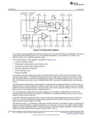
This application note describes a new integrated subsystem that contains the control circuitry, as well as
the switching elements, required for constructing switching regulator systems.
Contents
1 Introduction .................................................................................................................. 2
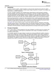
2 Principle of Operation ...................................................................................................... 2
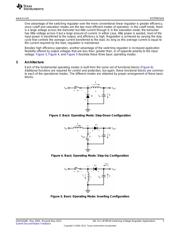
3 Architecture .................................................................................................................. 3
4 Analysis—Step-Down Operation .......................................................................................... 5
5 Analysis—Step-Up Operation ............................................................................................. 7
6 Analysis—Inverting Operation ............................................................................................. 9
7 Design—Step-Up Regulator ............................................................................................. 12
8 Design—Step-Down Regulator .......................................................................................... 14
9 Design—Inverting Regulator ............................................................................................. 16
10 Analysis and Design of the Inductor .................................................................................... 19
11 Selection of Switching Components .................................................................................... 20
12 Selection of Output Filter Capacitors ................................................................................... 20
13 EMI .......................................................................................................................... 20
14 Design Equations .......................................................................................................... 21
List of Figures
1 Switching System ........................................................................................................... 2
2 Regulator System Block Diagrams ....................................................................................... 2
3 Basic Operating Mode: Step-Down Configuration...................................................................... 3
4 Basic Operating Mode: Step-Up Configuration ......................................................................... 3
5 Basic Operating Mode: Inverting Configuration......................................................................... 3
6 Functional Block Diagram.................................................................................................. 4
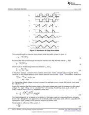
7 Waveforms for Step-Down Mode ......................................................................................... 6
8 Waveforms for Step-Up Mode............................................................................................. 8
9 Voltage Inverter Waveforms ............................................................................................. 11
10 Step-Up Voltage Regulator............................................................................................... 11
11 Switching Regulator with 15V Input, 70V Output...................................................................... 14
12 Step-Down Voltage Regulator ........................................................................................... 15
13 Modified Step-Down Regulator with 5A, 5V Output................................................................... 16
14 Inverting Regulator ........................................................................................................ 18
List of Tables
1 LM78S40 Design Formulae.............................................................................................. 21
All trademarks are the property of their respective owners.
1
SNVA026B–May 2004–Revised May 2013 AN-711 LM78S40 Switching Voltage Regulator Applications
Submit Documentation Feedback
Copyright © 2004–2013, Texas Instruments Incorporated
Verzeichnis