


herunterladen
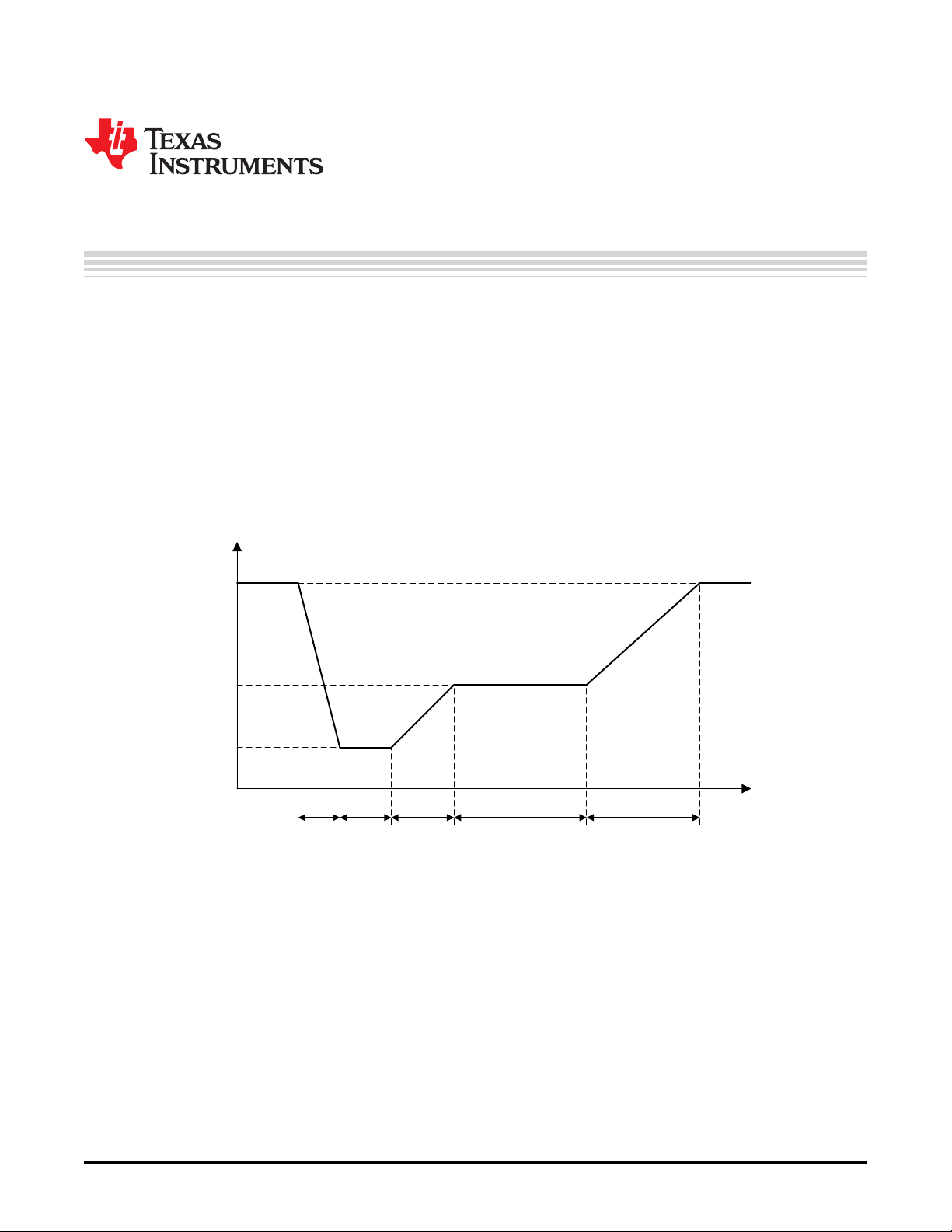
12 V
6 V
3 V
5 ms
15 ms to
40 ms 50 ms 0.5 s to 20 s 5 ms to 100 ms
time
Supply
Application Report
SNVA728–May 2015
Maintaining Output Voltage Regulation During Automotive
Cold-Crank with LM5175 Buck-Boost
VijayChoudhary
Designing electronics to operate from a 12-V car supply is challenging. The 12-V battery supply voltage
can range from 9-16V under normal operation depending on charge and load variation. However, the
transient battery voltage range can be much wider. One of these conditions is cold-crank that happens
when the battery is trying to energize the starter-motor circuits on the internal combustion engine.
Traditionally, only a few critical functions were required to ride through the cold-crank. Increasing car
manufacturers are making more features available through cold-cranks for better driver experience and
safety.
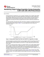
The cold-crank profile is described by ISO 7637-2 (test pulse 4). Individual car manufacturers have similar
cold-crank profiles with the supply rail dropping to 3 V or lower depending on the location of the load. An
example cold-crank profile is shown in Figure 1. The actual voltage levels and time intervals are
manufacturer specific.
Figure 1. A Representative Startup (Cold-crank) Test Profile for Car Supply with 12-V Battery
To keep the safety and convenience functions such as navigation, entertainment, dashboard, LED break
lights and headlights working through drops in the battery profile, the dc-dc converter supplying these
loads must be able to maintain regulation even when the 12-V supply voltage drops below the required
output voltage.
The LM5175, a 4-switch buck-boost controller, can maintain regulation even at supply voltages dropping
below 3 V. With an absolute maximum voltage rating of 60 V, it can survive load dump transients with
ease. In addition, the LM5175 uses a single inductor buck-boost topology to provide small solution size
and higher efficiency compared to Flyback or SEPIC. The 4-switch buck-boost solution employs
synchronous rectification for both buck and boost modes of operation which results in significant efficiency
advantage for high power solutions compared to competing topologies.
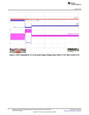
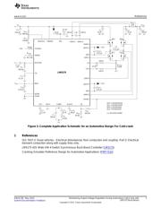
A LM5175 based 5 V / 7.5 A buck-boost converter is shown in Figure 3 with an operating input voltage
range of 3 V to 20 V with the ability to withstand load dump transients up to 42 V. Figure 2 shows a cold-
crank test condition. The converter maintains the output voltage even when the input supply voltage drops
below 3 V.
1
SNVA728–May 2015 Maintaining Output Voltage Regulation During Automotive Cold-Crank with
LM5175 Buck-Boost
Submit Documentation Feedback
Copyright © 2015, Texas Instruments Incorporated
Verzeichnis
- ・ Blockdiagramm on Seite 3
- ・ Anwendungsbereich on Seite 3 Seite 5