
herunterladen

Application Report
SNVA038B–May 2001–Revised April 2013
AN-1197 Selecting Inductors for Buck Converters
.....................................................................................................................................................
ABSTRACT
This application report provides design information to help select an off-the-shelf inductor for any
continuous-mode buck converter application.
Contents
1 Introduction .................................................................................................................. 2
2 Background: The Inductor Current Waveform .......................................................................... 2
3 Estimating Requirements for the Application ............................................................................ 3
3.1 Basic Method to Calculate L ...................................................................................... 3
3.2 Example 1 ........................................................................................................... 4
3.3 Voltseconds Method to Calculate L .............................................................................. 5
3.4 Example 2 ........................................................................................................... 5
3.5 Summary of Requirements ....................................................................................... 6
4 Characterizing an Off-the-Shelf Inductor ................................................................................. 6
4.1 Summary of Inductor Parameters ................................................................................ 9
5 Evaluating the Inductor for the Actual Application ...................................................................... 9
5.1 Example 3 ......................................................................................................... 10
6 Conclusions ................................................................................................................ 12
Appendix A Optimizing the Size of the Inductor ............................................................................ 15
List of Figures
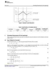
1 Inductor Current Waveform................................................................................................ 3
2 Design Flow Chart for Selection of Inductor ........................................................................... 14
3 Optimization Chart for Setting 'r'......................................................................................... 16
List of Tables
1 Specifications of Available Inductor ...................................................................................... 3
2 Complete Design Table for Evaluating the Inductor for a Given Application ...................................... 13
3 Optimization Table for Fixing Current Ripple Ratio ‘r' ................................................................ 16
All trademarks are the property of their respective owners.
1
SNVA038B–May 2001–Revised April 2013 AN-1197 Selecting Inductors for Buck Converters
Submit Documentation Feedback
Copyright © 2001–2013, Texas Instruments Incorporated
Verzeichnis
- ・ Technische Daten on Seite 3
- ・ Anwendungsbereich on Seite 18