
herunterladen
LM139/LM239/LM339 A
Quad of Independently
Functioning Comparators
Introduction
The LM139/LM239/LM339 family of devices is a monolithic
quad of independently functioning comparators designed to
meet the needs for a medium speed, TTL compatible com-
parator for industrial applications. Since no antisaturation
clamps are used on the output such as a Baker clamp or
other active circuitry, the output leakage current in the OFF
state is typically 0.5 nA. This makes the device ideal for
system applications where it is desired to switch a node to
ground while leaving it totally unaffected in the OFF state.
Other features include single supply, low voltage operation
with an input common mode range from ground up to ap-
proximately one volt below V
CC
. The output is an uncommit-
ted collector so it may be used with a pull-up resistor and a
separate output supply to give switching levels from any
voltage up to 36V down to a V
CE SAT
above ground (approx.
100 mV), sinking currents up to 15 mA. In addition it may be
used as a single pole switch to ground, leaving the switched
node unaffected while in the OFF state. Power dissipation
with all four comparators in the OFF state is typically 4 mW
from a single 5V supply (1 mW/comparator).
Circuit Description
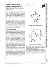
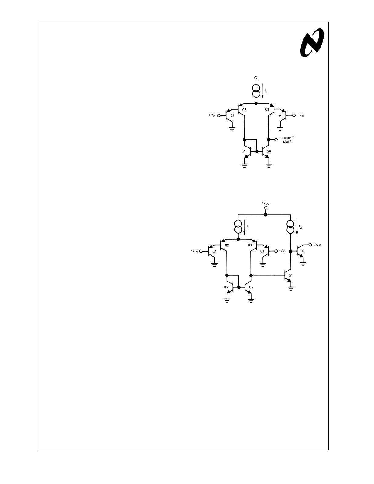
Figure 1 shows the basic input stage of one of the four
comparators of the LM139. Transistors Q
1
through Q
4
make
up a PNP Darlington differential input stage with Q
5
and Q
6
serving to give single-ended output from differential input
with no loss in gain. Any differential input at Q
1
and Q
4
will be
amplified causing Q
6
to switch OFF or ON depending on
input signal polarity. It can easily be seen that operation with
an input common mode voltage of ground is possible. With
both inputs at ground potential, the emitters of Q
1
and Q
4
will
be at one V
BE
above ground and the emitters of Q
2
and Q
3
at 2 V
BE
. For switching action the base of Q
5
and Q
6
need
only go to one V
BE
above ground and since Q
2
and Q
3
can
operate with zero volts collector to base, enough voltage is
present at a zero volt common mode input to insure com-
parator action. The bases should not be taken more than
several hundred millivolts below ground; however, to prevent
forward biasing a substrate diode which would stop all com-
parator action and possibly damage the device, if very large
input currents were provided.
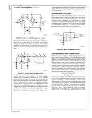
Figure 2 shows the comparator with the output stage added.
Additional voltage gain is taken through Q
7
and Q
8
with the
collector of Q
8
left open to offer a wide variety of possible
applications. The addition of a large pull-up resistor from the
collector of Q
8
to either +V
CC
or any other supply up to 36V
both increases the LM139 gain and makes possible output
switching levels to match practically any application. Several
outputs may be tied together to provide an ORing function or
the pull-up resistor may be omitted entirely with the com-
parator then serving as a SPST switch to ground.
Output transistor Q
8
will sink up to 15 mA before the output
ON voltage rises above several hundred millivolts. The out-
put current sink capability may be boosted by the addition of
a discrete transistor at the output.
The complete circuit for one comparator of the LM139 is
shown in Figure 3. Current sources I
3
and I
4
are added to
help charge any parasitic capacitance at the emitters of Q
1
and Q
4
to improve the slew rate of the input stage. Diodes D
1
and D
2
are added to speed up the voltage swing at the
emitters of Q
1
and Q
2
for large input voltage swings.
00738501
FIGURE 1. Basic LM139 Input Stage
00738502
FIGURE 2. Basic LM139 Comparator
National Semiconductor
Application Note 74
January 1973
LM139/LM239/LM339—A Quad of Independently Functioning Comparators AN-74
© 2002 National Semiconductor Corporation AN007385 www.national.com