

herunterladen
1
SBOA160A–July 2016–Revised December 2016
Submit Documentation Feedback
Copyright © 2016, Texas Instruments Incorporated
Low-Drift, Precision, In-Line Motor Current Measurements With Enhanced
PWM Rejection
Scott Hill, Current Sensing Products
____________________________________________________
Low-Drift, Precision, In-Line Motor Current Measurements
With Enhanced PWM Rejection
Scott Hill, Current Sensing Products
The demand for higher efficiency systems continues to
increase, leading to direct pressure for improvement in
motor operating efficiency and control. This focus
applies to nearly all classes of electric motors including
those used in white goods, industrial drives and in
automotive applications. The operational
characteristics of the motor fed back into the control
algorithm are critical to ensure the motor is operating
at its peak efficiency. Phase current is one of these
critical diagnostic feedback elements used by the
system controller enabling optimum motor
performance.
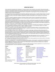
Due to the continuity of the measurement signal and
direct correlation to the phase currents, an ideal
location to measure the motor current is directly in-line
with each phase as shown in Figure 1. Measuring
current in other locations, such as the low-side of each
phase, requires recombination and processing before
meaningful data can be utilized by the control
algorithm.
Figure 1. In-Line Current Sensing
The drive circuitry for the motor generates pulse width
modulated (PWM) signals to control the motor’s
operation. These modulated signal subject the
measurement circuitry placed in-line with each motor
phase to common-mode voltage transitions that can
switch between large voltage levels over very short
time periods. An ideal amplifier would have the ability
to completely reject the common-mode voltage
component of the measurement and only amplifier the
differential voltage corresponding to the current flowing
through the shunt resistor. Unfortunately, real-world
amplifiers are not ideal and are influenced by the large
PWM-driven input voltage steps. Because real-world
amplifiers do not have infinite common-mode rejection
potentially large, unwanted disturbances appear at the
amplifier output corresponding to each input voltage
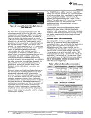
step as shown in Figure 2. These output disturbances,
or glitches, can be very large and take significant time
to settle following the input transition depending on the
characteristics of the amplifier.
Figure 2. Typical Output Glitch From Large Input
V
CM
Step
A common approach to this measurement is to select
a current sense amplifier with a wide bandwidth. In
order to stay above the audible frequency range,
modulation frequencies ranging from 20kHz to 30kHz
are typically selected. Amplifier selection for making in-
line current measurements in these PWM-driven
applications targets amplifiers with signal bandwidths
in the 200kHz to 500kHz range. The selection of the
amplifier was not historically based on actual signal
bandwidth which are significantly lower than the PWM
signal. The higher amplifier bandwidths were selected
to allow the output glitch to settle quickly following an
input voltage transition.
The INA240 is a high common-mode, bi-directional
current sense amplifier designed specifically for these
types of PWM-driven applications. This device
approaches the problem of measuring a small
differential voltage in the presence of large common-
mode voltage steps using integrated enhanced PWM
rejection circuitry to significantly reduce the output
disturbance and settle quickly. Standard current sense
amplifiers rely on a high signal bandwidth to allow the
output to recover quickly following the step, while the
INA240 features a fast current sense amplifier with
internal PWM rejection circuitry to achieve an
improved output response with reduced output
disturbance. Figure 3 illustrates the improved response
of the INA240 output due to this internal enhanced
PWM rejection feature.