
herunterladen
VISHAY DALE
Magnetics
Application Note
Selecting IHLP Composite Inductors for Non-Isolated
Converters Utilizing Vishay’s Application Sheet
APPLICATION NOTE
Revision: 08-Nov-11
1
Document Number: 34250
For technical questions, contact: magnetics@vishay.com
THIS DOCUMENT IS SUBJECT TO CHANGE WITHOUT NOTICE. THE PRODUCTS DESCRIBED HEREIN AND THIS DOCUMENT
ARE SUBJECT TO SPECIFIC DISCLAIMERS, SET FORTH AT www.vishay.com/doc?91000
www.vishay.com
INTRODUCTION
This application note will provide information to assist in the
specification of IHLP composite inductors based on given
operating conditions utilizing Vishay's IHLP application
sheets. It is assumed that the designer has a basic
understanding of non-isolated dc-to-dc converters as this is
not a design exercise in that family of converters. That being
said, tools will be introduced to allow the designer to select
an IHLP inductor and estimate its performance in their
applications. These tools will work for buck, boost and
buck/boost topologies. A set of application sheets will be
provided containing all the relevant constants and equations
needed for the selection process. This process is an
estimation only and all parts should be verified in their
application. It is also understood that the application sheets
are a work in progress and some of the data is estimated
through calculation. The estimated data will be highlighted
on the application sheets.
BACKGROUND
The IHLP inductor is constructed using an “open” or “air
coil” inductance coil. The two ends of the coil are connected
to a lead frame that acts as a means of transport through the
manufacturing operation at Vishay, and as the final
termination pads when the part is singulated from the lead
frame. A powdered iron core is pressed around the inductor
coil after the inductor coil is welded to the lead frame. The
characteristics of the powdered iron enhance the magnetic
properties of the inductor and also give the inductor its final
shape or footprint.
The composite inductor is essentially built backwards from
a conventional inductor. In a conventional inductor the
magnet wire is wound either directly on the core as in a
toroid, or wound on a bobbin with the core halves inserted
into it as in “E” style cores. Since each IHLP size and value
has a unique coil dimension varying in outside and inside
diameter and height, each inductor has different geometric
parameters. This means that core constants must be
calculated for each inductor size and value.
The only consistent item in a series of inductors will be the
performance of the iron powder from value to value;
therefore, the core loss constants for the material will remain
the same. There are, however, different iron powders used
in different product lines to cover a wider range of operating
conditions. Within these IHLP product lines the same
inductance values do not use the same air coil, which means
constants will be required not only for geometry but for
material as well. What it comes down to is that each inductor
has its own unique parameters even within the same family
size.
Composite inductors are frequently used in non-isolated
dc-to-dc converters. This is not an issue, however the
waveforms associated with them are not in line with
conventional thinking. Core loss characterization and the
resulting data are often determined using sinusoidal
excitation. Dc-to-dc converters on the other hand do not
operate with sine waves, instead they use a pulsed DC
waveform. This means that the current waveform in the
inductor determining core loss will be a triangular wave, not
a sine wave. This difference will need to be compensated for
in the core loss calculations.
Increasingly, dc-to-dc converters are being asked to
operate at higher ambient temperatures. This in turn
requires the inductor to operate at the higher temperature in
addition to its own temperature rise incurred due to power
losses. It is known that iron powder exhibits the effects of
aging at higher temperatures in the form of increased core
losses. These losses must be accounted for during the
design process in order for a composite inductor to be used
at temperatures in excess of 125 °C. The effects of thermal
aging can be minimized by simply limiting the maximum
inductor temperature to 125 °C or less.
SELECTION TOOLS
Criteria
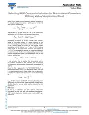
Start the inductor selection process by establishing the
selection criteria for the part. Composite inductors have
a recommended maximum component temperature of
125 °C. Subtracting the ambient temperature will give us
the maximum allowed temperature rise for the part. If this
number should exceed 40 °C it is recommended that 40 °C
be used for the allowed temperature rise. Core losses
should be limited to
1
/
3
of the total losses to mitigate any
aging effects associated with the powdered iron in the core
at elevated temperatures. Data sheets list a heat rated
current (I
HEAT
) as a parameter, which represents the current
needed to produce a certain temperature rise indicated on
the data sheet. This temperature rise is typically measured
using DC current and is due to copper losses only and does
not take into account core loss. However, this information is