


herunterladen

Maxim > Design Support > Technical Documents > Application Notes > Amplifier and Comparator Circuits > APP 69
Keywords: positive supply current, monitoring, load current, power supply, opamp, operational amplifiers,
op amps
APPLICATION NOTE 69
Micropower Circuit Monitors Positive Supply
Current
Jul 09, 1998
Abstract: The following application note shows a circuit that converts the load current of a positive power
supply into a ground referenced signal voltage using the ICL7612 operational amplifier.
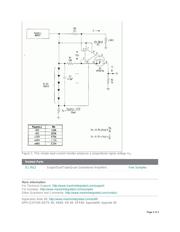
The inexpensive circuit of Figure 1 converts the load current of a positive power supply to a ground-
referenced signal voltage, without recourse to the instrumentation amplifier, extra power supply, and
matched sets of resistors typical of such circuits. The output current I
O
(proportional to supply current)
flows through R
O
to produce V
O
. Because I
O
is generated by a true current source, you can reference
V
O
to ground or to any reasonable level within the supply range. The measurement is independent of
variations in the supply voltage.
Because the op amp's common-mode range includes the supply rails, it can sense small voltages near
the positive rail, such as those across R
S
. Feedback resistor R
F
should equal 100R
S
or 1000R
S
. The op
amp drives P-channel MOSFET Q
1
, whose drain-source current produces a voltage across R
F
equal to
that across R
S
, subject to an error of ±V
OS
. As a result,
I
O
= (I
L
R
S
)(1/R
F
) and,
V
O
= (I
L
R
S
)(R
O
/R
F
).
The component values shown provide a V
O
range of 0 to 1V for the supply-current range 0 to 1A. You
can add a trimming potentiometer to null V
OS
. The remaining gain error depends on the tolerance of R
S
,
R
F
or R
O
. The op amp draws 20µA and operates with a voltage as low as 2.5V. This op amp supply is
produced by the five diodes, which are biased by R
Z
and the input supply voltage as shown in the table.
Page 1 of 3