
herunterladen
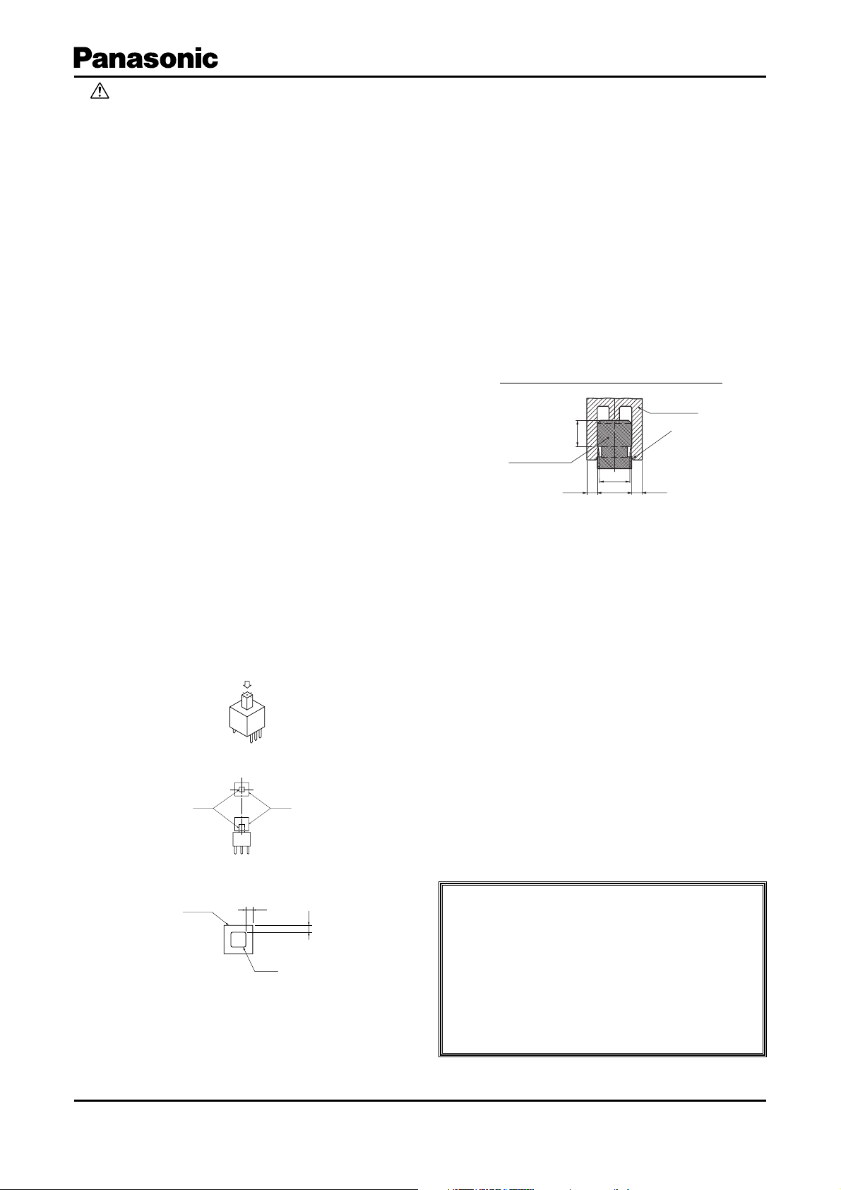
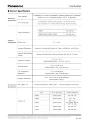
Design and specifi cations are each subject to change without notice. Ask factory for the current technical specifi cations before purchase and/or use.
Should a safety concern arise regarding this product, please be sure to contact us immediately.
Push Switches
■
Application
Notes
When using our Push Switches, please observe the
following items (“prohibited items”) and be cautious of
the following in order to prevent dangerous accidents and
de te ri o ra tion of performance.
1. Prohibited items and notes on mounting
1. When soldering (including preheating), do not solder in
the locked condition.
2. When soldering using a soldering iron, soldering
conditions vary with the tip shape of the soldering
iron, wattage, and PWB thickness. Thoroughly
check the con di tions in advance, including the heat
resistance rat ing of the solder.
3. Do not apply a load to terminals when soldering. Care
should be taken in this regard because a load may
de te ri o rate electric and mechanical char ac ter is tics.
4. Since the push switches are not sealed, do not wash
them.
5. When mounting a push switch to a through-hole type
PWB, the infl uence of thermal stress on the switch is
greater than that on one-sided PWB. Be sure to check
the infl uence as well as the heat re sis tance rating of
the solder.
2. Notes on circuit conditions
1. To ensure reliability, use switches within the rated range,
as designated in “Product Specifi cations for Information.”
2. To avoid malfunction of a set due to bounce generated
by turning the switch ON and OFF, and/or due to
chat ter generated by external vibrations, etc., take the
following into consideration in design.
●
Read contact multiple times.
(In Case of microcomputer Processing )
●
Set a delay time.
(Recommendation: 3 or more times of reading with
the cycle of 3 ms or over)
●
Prepare a CR integrating circuit.
(Recommendation: A time constant of 6 ms or over )
3. When circuits of a two-circuit type are connected in
par al lel, switching timing (non-shorting, etc.) described
in the spec i fi ca tions is not assured.
3. Prohibited items and notes on mounting and operating
conditions
1. In principle, operate the center of the lever.
2. For mounting an operation button:
1) Design so that the button is mounted to the cen ter
of the lever.
2) Design a set so that the gap (a) between the
cabinet and the button is as small as possible.
(a)=0.1 to 0.3 mm
3) Design so that the load in removal and mounting of
the button is within the range of the switch's strength
rating of the operational part.
3. If multiple switches are placed side by side, or a
switch is placed near another part, the gap be tween
the switch and the adjacent switch/part must be at
least 1 mm to prevent affect of fl ux and to ensure
prop er insulation distance.
4. Design and use so that external stress is not con tin u ous ly
applied to the soldering parts in a set. Ex ter nal stress
may cause pattern peeling and solder cracks on a PWB.
5. When mounting a switch, check the ON/OFF po si tion.
6. Contact lubricant, which is used in push switches,
may fl ow out to the exterior of the switch due to the
struc ture. For design review, suffi ciently check the
operating conditions.
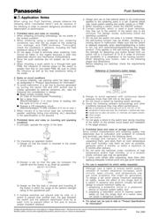
7. D o n o t pull the s w itch rod while it is locked. Oth er wise,
the self-lock ing func tion may be broken, re sult ing in a
lock ing fail ure or mal func tion. Make sure that the switch
is re leased es pe cial ly when attaching/de tach ing a but ton
to the rod and as sem bling/dis as sem bling the target
prod uct. (This ap plies to the self-lock ing switches) Set
the strength for de tach ing your but ton (knob) from our
switch rod to a max i mum of 10 N in order to min i mize
the pos si bil i ty of a break down of the locking func tion.
When de sign ing your but ton, re fer to the following
shape and dimensions.
Before adopting our switches, check the requirements
carefully.
8. Design to avoid operation with continuous lateral
pressure (more than 500 mN on the lever).
9. Do not mount a switch by bending switch terminals.
Avoid the following ambient surroundings and other
con di tions because they may affect performance:
●
Under an atmosphere of corrosive gas such as Cl
2
, H
2
S, NO
x
, or SO
2
●
In atmospheres of residual water drops, dew condensation, or adhesive water drops
●
In liquids such as water, salt solution, oil, chem i cals, and organic solvents
●
In direct sunlight
●
In dusty locations
Do not apply a shock to the switch lever during mounting
of the switch on the printed circuit board and installation
in the target product.
4. Prohibited items and notes on storage con di tions
Since contact characteristics and soldering quality may
de te ri o rate due to sulfuration and oxidation of con tacts
and terminals, pay heed to the following items.
1. For sto rage and transport of the switches, avoid
unpacking them, and store them at room tem per a ture
and room humidity. Use them as soon as pos si ble,
gen er al ly within 3 months, or within a max i mum of
6 months after de liv ery.
2. Do not store the switches under conditions of high
tem per a ture and/or high humidity, or in a location
where cor ro sive gas may be generated.
3. If some units remain after unpacking, store them after
applying adequate moisture-proof and gas-proof treat ment.
5. For use in equipment for which safety re quest ed
Although care is taken to ensure switch quality,
vari a tion of contact resistance (increase), short
circuits, open cir cuits, and temperature rise
are some prob lems that might be generated.
To de sign a set which places maximum emphasis
on safety, review the affect of any single fault of
a switch in advance and perform virtually fail-safe
design to ensure max i mum safety by:
1. preparing a protective circuit or a protective
device to improve system safety, and
2. preparing a redundant circuit to improve sys tem
safe ty so that the single fault of a switch does
not cause a dangerous situation.
6. For actual use, be sure to refer to “Product Spec i fi ca tions
for Information.”
10.
Reference of Customer's button design
11.
PUSH
Lever Button
(a)
(a)
Cabinet
Button
(2.5)
(3.0)
(3.3)
(0.6)
Switch rod top
Customer's
button
(0.6)
(R1.2)
Feb. 2008