
herunterladen

© 2005 Microchip Technology Inc. DS00984A-page 1
AN984
INTRODUCTION
This application note demonstrates how you use the
dsPIC30F MCU to control an AC Induction Motor (ACIM).
The discussion is based on the dsPICDEM™ MC Motor
Control Development System, but you can use your own
hardware if you choose. The dsPICDEM MC Motor
Control Development System has electrical isolation and
is fully self-protected against Faults. With these features,
you can safely develop a motor control application and
also avoid damage to hardware by software errors.
The code provided in this application note is a simple
example that provides basic variable speed control of
an ACIM. It will help you learn about the dsPIC30F
architecture and the basics of ACIM control
Recommended Hardware
The code presented in this application note can be run
on the following Microchip equipment:
• MPLAB
®
ICD 2 In-Circuit Debugger and Device
Programmer (Part# DV164005)
• dsPICDEM MC1 Motor Control Development
Board (Part# DM300020)
• dsPICDEM MC1H 3-Phase High-Voltage Power
Module (Part# DM300021)
• 3-Phase ACIM High-Voltage Motor (208/460V)
(Part# AC300021)
If you prefer, you can supply your own 3-phase or
single-phase ACIM. The recommended power range is
1/6-1/2 HP.
Documents for Further Reading
These application notes provide useful background
information:
•
AN887, “AC Induction Motor Fundamentals”
(DS00887)
•
AN889, “VF Control of 3-Phase Induction Motors
Using PIC16F7X7 Microcontrollers”
(DS00889)
•
AN900, “Controlling 3-Phase AC Induction Motors
Using the PIC18F4431”
(DS00900)
•
AN908, “Using the dsPIC30F for Vector Control of
an ACIM”
(DS00908)
BACKGROUND
Variable speed ACIM drives have evolved from
industrial control applications. Wound DC motors were
preferred in the past because they were easier to
control. The motor current is simply varied to adjust the
torque output and motor speed. However, these DC
motors do have some disadvantages. DC motors used
in industrial applications need to be periodically over-
hauled to replace worn brushes and rotor windings.
Since the rotor windings of a DC motor are inside the
motor, it is more difficult to keep them cool.
An ACIM has a simple rotor construction and does not
use brushes. For these reasons, an ACIM is more
durable than a DC motor. The only mechanical compo-
nents that need to be serviced are the rotor bearings.
The rotor is much more tolerant of heat because it is
simply a steel cage with magnetic laminations. The
durability of the ACIM makes it an attractive choice.
Variable speed control of an ACIM is conceptually very
simple. The frequency and amplitude of the drive
voltage must be varied to change the motor speed.
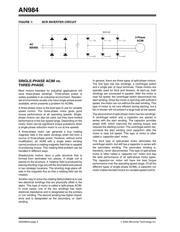
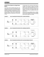
Early ACIM drives used SCR devices connected to the
motor as shown in Figure 1. By firing each SCR at the
appropriate time, a very crude sinusoidal voltage can
be generated on the motor phases. These types of
circuits are often called ‘six-step’ drives because there
are six different ways that the SCR devices can be
energized to produce motor currents. However, the
high harmonic content of the six-step drive causes high
heat dissipation and does not deliver good
performance at low frequencies.
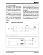
Semiconductor technology has drastically improved
since the days of six-step drives. SCR devices are now
replaced with MOSFET or IGBT devices that can be
switched at relatively high frequencies with minimal
power loss. These devices can be controlled using
PWM signals to generate continuously variable drive
voltages and currents.
Author: Steve Bowling
Microchip Technology
An Introduction to AC Induction Motor Control
Using the dsPIC30F MCU