
herunterladen

Maxim > Design Support > Technical Documents > Application Notes > Digital Potentiometers > APP 4051
Keywords: digital potentiometer, analog controlled resistance, voltage controlled resistance
APPLICATION NOTE 4051
Using an Analog Voltage to Control a Digital
Potentiometer
By: Hrishikesh Shinde
May 15, 2008
Abstract: In some applications a digital potentiometer with an I²C interface must be controlled by a
continuously varying analog signal. This application note addresses this requirement, and provides a
simple design solution. The principle presented here is versatile and can be used in multiple applications.
A similar article appeared in the March 20, 2008 edition of EDN magazine.
Introduction
This application note describes a simple method that uses an external analog voltage to change the
resistance of a digital potentiometer. The Microchip PIC12F683 microcontroller is used to make the
conversion from an analog voltage to an I²C stream, which is then used to control the digital
potentiometer. The DS1803 digital potentiometer serves as the example device and a minimum number
of external components is used in this application. The ideas presented here can be applied to other
control inputs and other digital potentiometers/resistors.
Hardware Configuration
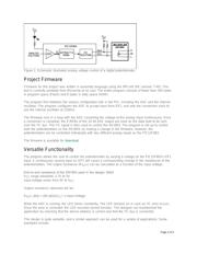
Figure 1 shows the schematic for the control circuit that uses the PIC12F683. Four of the
microcontroller's six GPIOs are used to control output signals on SDA, SCL, and a single LED, and to
accept one analog input.
Output signals on SDA, SCL, and the LED are assigned to GP5, GP4, and GP0, respectively. SDA and
SCL have 4.7kΩ pull-up resistors to V
DD
and connect directly to the DS1803's SDA and SCL pins. The
microcontroller's GP1 IO is assigned as the analog input pin. Jumpers are provided for selecting address
pins, separating the shared V
CC
(V
DD
), and isolating SDA and SCL.
Page 1 of 5