

herunterladen

Maxim > Design Support > Technical Documents > Application Notes > Digital Potentiometers > APP 169
Maxim > Design Support > Technical Documents > Application Notes > General Engineering Topics > APP 169
Maxim > Design Support > Technical Documents > Application Notes > Interface Circuits > APP 169
Keywords: 3-wire interface, SPI to 3-wire, SPI bus, digital potentiometers, digital pots, SPI interface, shift register
APPLICATION NOTE 169
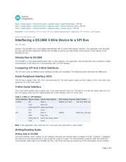
Interfacing a DS1868 3-Wire Device to a SPI Bus
Dec 26, 2001
Abstract:
The
DS1868 uses a dual digital potentiometer with a 3-wire (shift register) interface. This application note describes
the logic and firmware required to interface the DS1868, as well as any other Dallas Semiconductor 3-wire devices to the
Motorola SPI bus.
Introduction to DS1868
The DS1868 is a dual digital potentiometer with a 3-wire interface. This application note will describe how to interface a Dallas
Semiconductor 3-wire device to a microcontroller with a SPITM interface.
Comparing SPI And 3-Wire Interfaces
The SPI and 3-wire are different serial interfaces but they are compatible. The following section describes the differences.
Serial Peripheral Interface (SPI)
The SPI has 4 signals: SDO, SDI, SCK, and active-low SS. The SDO signal is data out, SDI is data in, SCK is the clock, and
active-low SS is the slave select.
3-Wire Serial Interface
The 3-wire serial interface has 4 signals: DQ, Cout, active-low RST and CLK. The data in is on the DQ signal, data out is on
the Cout signal, active-low RST signal enables the 3-wire interface, and CLK is the clock.
Table 1. 3-Wire vs. SPI Interface.
Serial Interface Signal names Signal Descriptions BUS Speed (Typical) Data Format
3-WIRE DQ Data In 500kHz to 5 MHz LSB first, MSB last
Cout Data Out
active-low RST active-low Reset
CLK Clock
SPI SDI Data In 10MHz MSB first, LSB last
SDO Data Out
active-low SS active-low Slave Select
SCK Clock
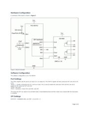
Note: In this application note, active-low SS is not used (only used when in slave mode).
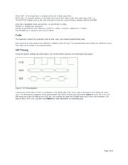
Writing/Reading Bytes
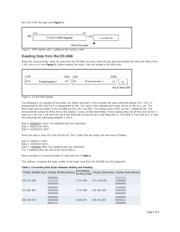
Writing Data to DS1868
The microcontroller, which contains an SPI interface, transmits and receives data in multiples of 8 bits. Therefore, 7 additional
bits need to be sent along with the 17 bits of data for a total of 3 bytes. The microcontroller sends the MSB first. When the
microcontroller writes data to the DS1868, the first 7 bits of the first byte are pushed out of the shift register and b0 contains
Page 1 of 9