
herunterladen

Maxim > Design Support > Technical Documents > Application Notes > 1-Wire
®
Devices > APP 3930
Maxim > Design Support > Technical Documents > Application Notes > General Engineering Topics > APP 3930
Maxim > Design Support > Technical Documents > Application Notes > Measurement Circuits > APP 3930
Keywords: Theta JA, Theta JC, theta-ja, theta-jc, self heating, thermal dissipation, heat dissipation, power dissipation, thermal resistance, junction to case, junction to
ambient, temperature, sensor, temperature sensor, thermal
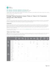
APPLICATION NOTE 3930
Package Thermal Resistance Values (Theta JA, Theta JC) for Temperature
Sensors and 1-Wire Devices
Nov 16, 2006
Abstract:
Two common
thermal-resistance values measured for IC packages are junction to ambient (Theta JA) and junction to case (Theta JC). These parameters
are useful for calculating maximum power dissipation and self-heating, and for comparing package types. Theta JA and Theta JC values are presented here for
select Maxim temperature sensors and 1-Wire® devices. Examples for calculating the values are given.
Introduction
Managing heat in electronic systems is crucial for ensuring product reliability. Integrated circuits (ICs) exposed to high temperatures can fail or malfunction in the
field, thus requiring costly repair or redesign. Typical thermal-resistance parameters give the resistance from the IC junction to some external reference point. Two
popular measured parameters are the junction to ambient (Theta JA) and junction to case (Theta JC) values. These parameters have units of °C/W, indicating the
temperature rise in °C for a given power dissipation. Knowing these package thermal-resistance values can help the system designer evaluate the thermal
performance of different package types.
This application note lists Theta JA and Theta JC values for select Maxim temperature sensors and 1-Wire® devices organized by package and device type. Some
example calculations are presented.
Theta JA and Theta JC Values
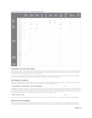
Tables 1 and 2 show the Theta JA and Theta JC values available for select Maxim temperature sensors. The values were obtained using the JEDEC standard test
methodology for two- and four-layer boards. Board sizes, trace layouts, and environmental conditions were all measured. Further information on the JEDEC
standards can be found at www.jedec.org under the JESD51 standard.
Table 1. Theta JA and Theta JC Values for 1-Wire Devices
8-Pin
DIP
.300
8-Pin
SO.150
8-Pin
SO.208
3-
Pin
PR-
35
3-
Pin
T0-
92
3-Pin
SOT23
5-Pin
SOT23
8-Pin
µSOP/
µMAX®
8-Pin
µSOP
Ex.
Pad
24-Pin
TSSOP
.173
6-Pin
TSOC
.150
Two-
Layer
Board
Theta JA 110 170
221 97 82 166
Theta JB
250 140
Theta JC 40 40 130 82 41.9 15 37
Four-
Layer
Board
Theta JA
128.4 27.72 206.3 72 126.7
Theta JB
Theta JC 40 3.12 41.9 13 37
1-Wire
Devices
DS18B20
X X X
DS18B20-
PAR
X
DS18S20 X X
DS18S20-
PAR
X
DS1821 X X
DS1822 X X
DS1822-
PAR
X
DS1825 X
DS28EA00 X
DS2431 X X
Page 1 of 4