

herunterladen
© Semiconductor Components Industries, LLC, 2014
November, 2014 − Rev. 8
1 Publication Order Number:
D44VH/D
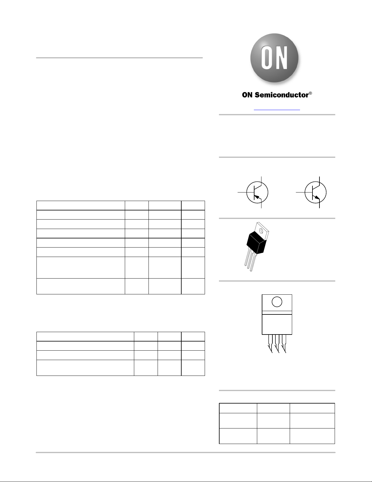
D44VH10(NPN),
D45VH10 (PNP)
Complementary Silicon
Power Transistors
These complementary silicon power transistors are designed for
high−speed switching applications, such as switching regulators and
high frequency inverters. The devices are also well−suited for drivers
for high power switching circuits.
Features
• Fast Switching
• Key Parameters Specified @ 100°C
• Low Collector−Emitter Saturation Voltage
• Complementary Pairs Simplify Circuit Designs
• These Devices are Pb−Free and are RoHS Compliant*
MAXIMUM RATINGS
Rating Symbol Value Unit
Collector−Emitter Voltage V
CEO
80 Vdc
Collector−Emitter Voltage V
CEV
100 Vdc
Emitter Base Voltage V
EB
7.0 Vdc
Collector Current − Continuous I
C
15 Adc
Collector Current − Peak (Note 1) I
CM
20 Adc
Total Power Dissipation
@ T
C
= 25°C
Derate above 25°C
P
D
83
0.67
W
W/°C
Operating and Storage Junction
Temperature Range
T
J
, T
stg
−55 to 150 °C
Stresses exceeding those listed in the Maximum Ratings table may damage the
device. If any of these limits are exceeded, device functionality should not be
assumed, damage may occur and reliability may be affected.
1. Pulse Width ≤ 6.0 ms, Duty Cycle ≤ 50%.
THERMAL CHARACTERISTICS
Characteristic Symbol Max Unit
Thermal Resistance, Junction to Case
R
q
JC
1.5 °C/W
Thermal Resistance, Junction to Ambient
R
q
JA
62.5 °C/W
Maximum Lead Temperature for Soldering
Purposes: 1/8″ from Case for 5 Seconds
T
L
275 °C
*For additional information on our Pb−Free strategy and soldering details, please
download the ON Semiconductor Soldering and Mounting Techniques
Reference Manual, SOLDERRM/D.
Device Package Shipping
ORDERING INFORMATION
MARKING DIAGRAM
15 A
COMPLEMENTARY SILICON
POWER TRANSISTORS
80 V, 83 W
x = 4 or 5
A = Assembly Location
Y = Year
WW = Work Week
G = Pb−Free Package
D44VH10G TO−220
(Pb−Free)
50 Units/Rail
D45VH10G TO−220
(Pb−Free)
50 Units/Rail
www.onsemi.com
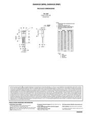
TO−220
CASE 221A
STYLE 1
1
2
3
4
D4xVH10G
AYWW
1
BASE
EMITTER 3
COLLECTOR 2, 4
1
BASE
EMITTER 3
COLLECTOR 2, 4
PNP NPN
Verzeichnis