
herunterladen
www.cypress.com Document No. 001-16634 Rev. *G 1
AN6081
Interfacing 90-nm Cypress Asynchronous SRAMs in Legacy Systems
Author: Anuj Chakrapani
Associated Project: No
Related Application Notes: None
AN6081 describes the potential issues faced when using the new-generation 90-nm Cypress SRAMs in applications
that rely on legacy 5-V processors. This application note also discusses the troubleshooting methods on output
voltage issues when migrating to the new devices. Usage recommendations when you opt to use Cypress SRAMs in
such applications are also provided.
Introduction
Applications have evolved from using 5-V power supply to
using 3-V and 1.8-V supply. Cypress’s Asynchronous
SRAM devices operate over all of these voltage ranges.
This application note discusses a case of incompatibility
between output voltage thresholds of 90-nm SRAM
devices and input voltage thresholds of processors or
controllers
that are interfaced with these SRAMs in legacy
5-V systems. A recommendation to use an old generation
Cypress SRAM is given to match the requirements in such
cases.
Note: The terms “Processor(s)” and “Controller(s)” are
used interchangeably in this document.
Logic Levels and Noise Margin
In digital electronics, a logic level is one of two possible
signal states. Four parameters define the logic levels for a
digital logic family: V
IL
, V
IH
, V
OL
, and V
OH
.
V
IL
defines the maximum voltage level that will be
interpreted as a ‘0’ by a digital input.
V
IH
defines the minimum voltage level that will be
interpreted as a ‘1’ by a digital input.
V
OL
defines the guaranteed maximum voltage level
that will appear on a digital output set to ‘0’.
V
OH
defines the guaranteed minimum voltage level
that will appear on a digital output set to ‘1’.
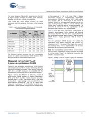
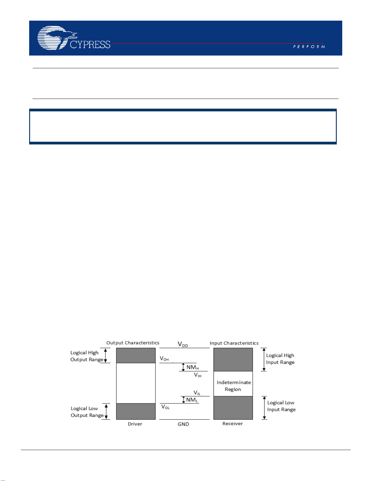
Noise margin (NM) is defined as the difference between
the valid logic output voltage of the driver IC and the valid
logic input voltage of the receiver IC. These are the
expressions for NM of devices.
NM
H
(Output high) = V
OH
[driver] - V
IH
[receiver]
NM
L
(Output low) = V
IL
[receiver] - V
OL
[driver]
Figure 1: Noise Margin
Verzeichnis
- ・ Technische Daten on Seite 3
- ・ Anwendungsbereich on Seite 1
- ・ Teilenummernliste on Seite 4