
herunterladen
Semiconductor Components Industries, LLC, 2013
June, 2013 − Rev. 11
1 Publication Order Number:
CAT5115/D
CAT5115
32‐tap Digital
Potentiometer (POT)
Description
The CAT5115 is a single digital POT designed as an electronic
replacement for mechanical potentiometers and trim pots. Ideal for
automated adjustments on high volume production lines, they are also
well suited for applications where equipment requiring periodic
adjustment is either difficult to access or located in a hazardous or
remote environment.
The CAT5115 contains a 32-tap series resistor array connected
between two terminals R
H
and R
L
. An up/down counter and decoder
that are controlled by three input pins, determines which tap is
connected to the wiper, R
W
. The wiper is always set to the mid point,
tap 15 at power up. The tap position is not stored in memory.
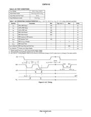
Wiper-control of the CAT5115 is accomplished with three input
control pins, CS
, U/D, and INC. The INC input increments the wiper
in the direction which is determined by the logic state of the U/D
input.
The CS
input is used to select the device.
The digital POT can be used as a three-terminal resistive divider or
as a two-terminal variable resistor. Digital POTs bring variability and
programmability to a wide variety of applications including control,
parameter adjustments, and signal processing.
For a pin-compatible device that recalls a stored tap position on
power-up refer to the CAT5114 data sheet.
Features
32-position Linear Taper Potentiometer
Low Power CMOS Technology
Single Supply Operation: 2.5 V − 6.0 V
Increment Up/Down Serial Interface
Resistance Values: 10 kW, 50 kW and 100 kW
Available in PDIP, SOIC, TSSOP, MSOP Packages
These Devices are Pb-Free, Halogen Free/BFR Free and are RoHS
Compliant
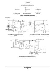
Applications
Automated Product Calibration
Remote Control Adjustments
Offset, Gain and Zero Control
Tamper-proof Calibrations
Contrast, Brightness and Volume Controls
Motor Controls and Feedback Systems
Programmable Analog Functions
http://onsemi.com
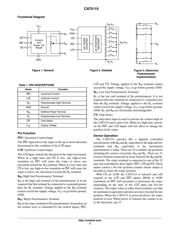
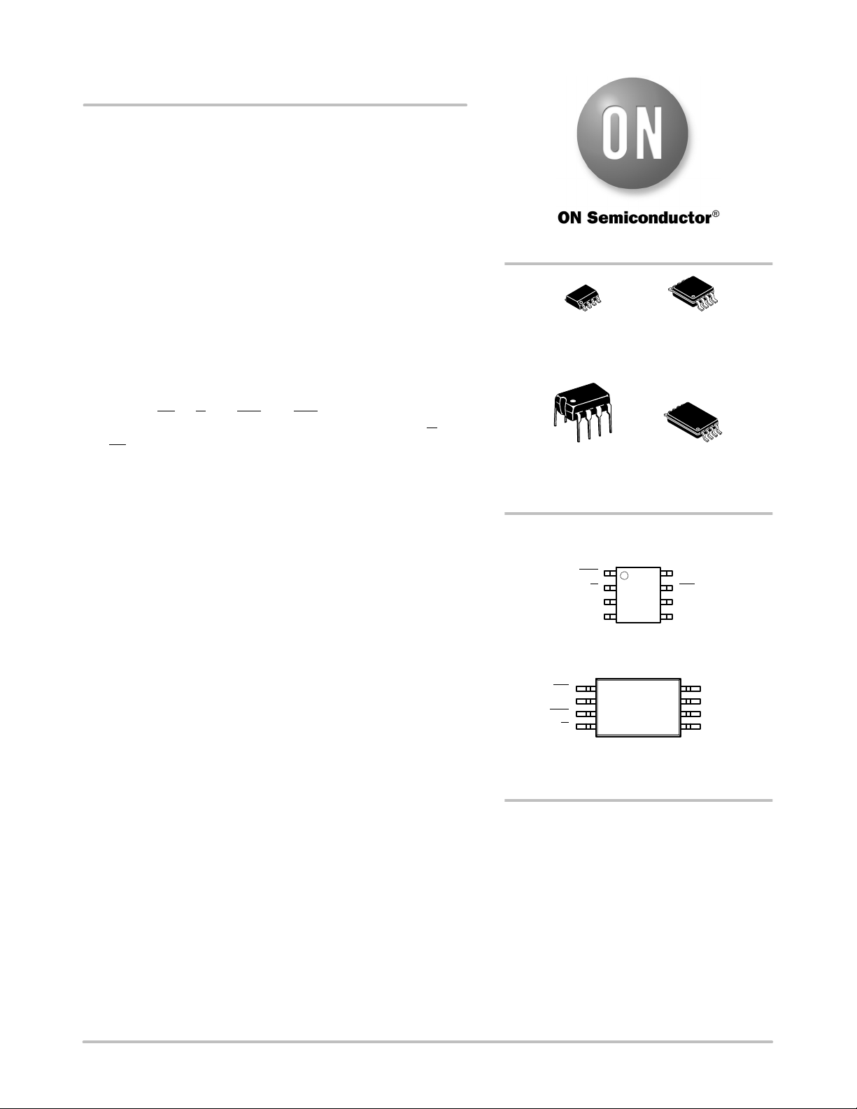
PIN CONFIGURATIONS
R
H
R
WB
R
L
U/D
INC
V
CC
CS
1
See detailed ordering and shipping information in the package
dimensions section on page 8 of this data sheet.
ORDERING INFORMATION
SOIC−8
V SUFFIX
CASE 751BD
MSOP−8
Z SUFFIX
CASE 846AD
GND
PDIP (L), SOIC (V), MSOP (Z)
PDIP−8
L SUFFIX
CASE 646AA
TSSOP−8
Y SUFFIX
CASE 948AL
TSSOP (Y)
(Top Views)
GND
R
H
U/D
INC
R
WB
CS
V
CC
R
L
1
Verzeichnis
- ・ Konfiguration des Pinbelegungsdiagramms on Seite 1 Seite 2
- ・ Abmessungen des Paketumrisses on Seite 9 Seite 10 Seite 11 Seite 12
- ・ Teilenummerierungssystem on Seite 1 Seite 8 Seite 12
- ・ Markierungsinformationen on Seite 12
- ・ Typisches Anwendungsschaltbild on Seite 2
- ・ Technische Daten on Seite 3 Seite 8
- ・ Anwendungsbereich on Seite 1 Seite 6
- ・ Elektrische Spezifikation on Seite 4
- ・ Teilenummernliste on Seite 8