
herunterladen
1
©
1999 Burr-Brown Corporation AB-137 Printed in U.S.A. January, 1999
®
ADD CURRENT LIMIT TO THE BUF634
By David Jones and Mark Stitt
Modern buffer amplifiers, such as the BUF634, are often
used with op amps to drive high-current demand loads such
as cables or electro-mechanical devices. BUF634 features
internal overload protection to prevent its destruction under
fault conditions. Internal current limit protects circuitry and
wirebonds from excessive current. Internal over-temp shut
down protects the device from excessive temperature rise by
shutting down the output drive before catastrophic chip
temperatures are reached (approximately 165°C).
The internal BUF634 current limit can allow output current
to exceed 500mA. In some applications, it is necessary to
limit the output current to a lower level to protect the load.
External current limit can be added to the BUF634 with the
addition of a current-sense resistor and a few other compo-
nents.
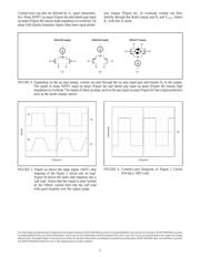
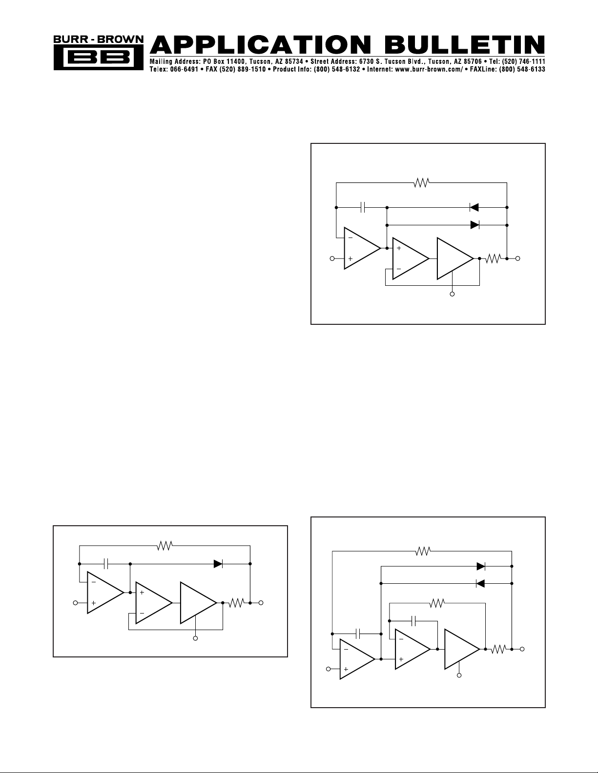
Figure 1 shows the basic circuit for BUF634 external current
limit. The BUF634 (A
3
) is connected in the feedback loop of
A
2
forming a precision closed-loop buffer—the output volt-
age of A
3
is equal to the input of A
2
. A current-sense resistor,
R
CL
, is connected from the buffer to the circuit output, V
OUT
.
The buffer and resistor are enclosed in the feedback loop of
A
1
with a diode connected across the A
2
, A
3
buffer. Output
current produces a voltage drop across R
CL
. Until the voltage
across R
CL
approaches the forward voltage drop of D
1
, the
overall loop amplifier, A
1
, maintains V
OUT
precisely equal
to V
IN
. As the voltage across R
CL
increases, drive current
from A
1
is diverted through D
1
to the output and current
limit is achieved. Output current limit is the sum of the
current limit of A
1
plus the forward voltage drop across D
1
divided by R
CL
. For bipolar current limit, back-to-back
diodes can be used as shown in Figure 2.
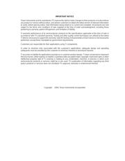
For stability, the bandwidth of A
2
must be less than approxi-
mately one-fourth the bandwidth of A
3
, and R
1
C
1
/(2π) must
be less than approximately one-fourth the bandwidth of A
2
.
With its bandwidth control pin unconnected, BUF634 band-
width is 20MHz typ. Connecting the bandwidth control pin
to V– increases bandwidth to approximately 160MHz.
In some cases, it may also be necessary to compensate the
A
2
– A
3
loop as shown in Figure 3. In this case, R
2
C
2
/(2π)
must be less than approximately one-fourth the bandwidth of
A
3
and R
1
C
1
must be less than (R
2
C
2
)/4.
R
1
D
2
R
2
1/2
OPA2277
1/2
OPA2277
BUF634
BW
A3
A2
A1
C
1
C
2
R
C1
10Ω
V
OUT
V–
V
IN
D
1
FIGURE 1. Current limit can be added to the BUF634 with
the addition of a current-sense resistor and a
few other components. Output current produces
a voltage drop across the current limit resistor,
R
CL
. As the voltage across R
CL
increases, drive
current from A
1
is diverted through D
1
to the
output and current limit is achieved.
FIGURE 2. Adding a second diode to the Figure 1 circuit
provides bipolar current limit. With the values
shown, current limit is approximately ±100mA.
FIGURE 3. In some applications, it may be necessary to add
compensation around the A
2
, A
3
loop.
R
1
D
1
1/2
OPA2277
1/2
OPA2277
BUF634
BW
A
3
A
2
A
1
C
1
R
CL
V
OUT
V–
V
IN
R
1
10kΩ
D
2
1/2
OPA2277
1/2
OPA2277
BUF634
BW
A
3
A
2
A
1
Overall I
LIMIT
≈ A
1
I
LIMIT
+ 0.7V/10Ω.
C
1
100pF
R
CL
10Ω
V
OUT
V–
V
IN
D
1
SBOA042