
herunterladen
1
SLUA790–November 2016
Submit Documentation Feedback
Copyright © 2016, Texas Instruments Incorporated
Using I
2
C Communications With the bq34110, bq35100, and bq34z100-G1
Series of Gas Gauges
All trademarks are the property of their respective owners.
Application Report
SLUA790–November 2016
Using I
2
C Communications With the bq34110, bq35100,
and bq34z100-G1 Series of Gas Gauges
............................................................................................................ BatteryManagement Solutions
ABSTRACT
This application report provides examples that illustrate the bit-transaction details of I
2
C commands used
with TI's bq34xxx series and bq35xxx series battery fuel gauges. The first two examples provide detailed
explanations of using I
2
C commands to read standard parameters and Control Subcommand parameters.
The first example shows how to implement a standard fuel gauge command that interrogates the gauge
for reading cell voltage. The second example shows the added bit transitions required to access a Control
Subcommand, specifically requesting firmware version information. Other I
2
C commands can be executed
in the same manner, using the methodology of these two examples. The final sections provide step-by-
step examples using the bqStudio I
2
C Master Control Panel to read and write parameters from these
gauges.
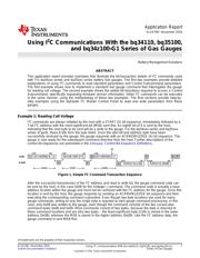
Example 1: Reading Cell Voltage
I
2
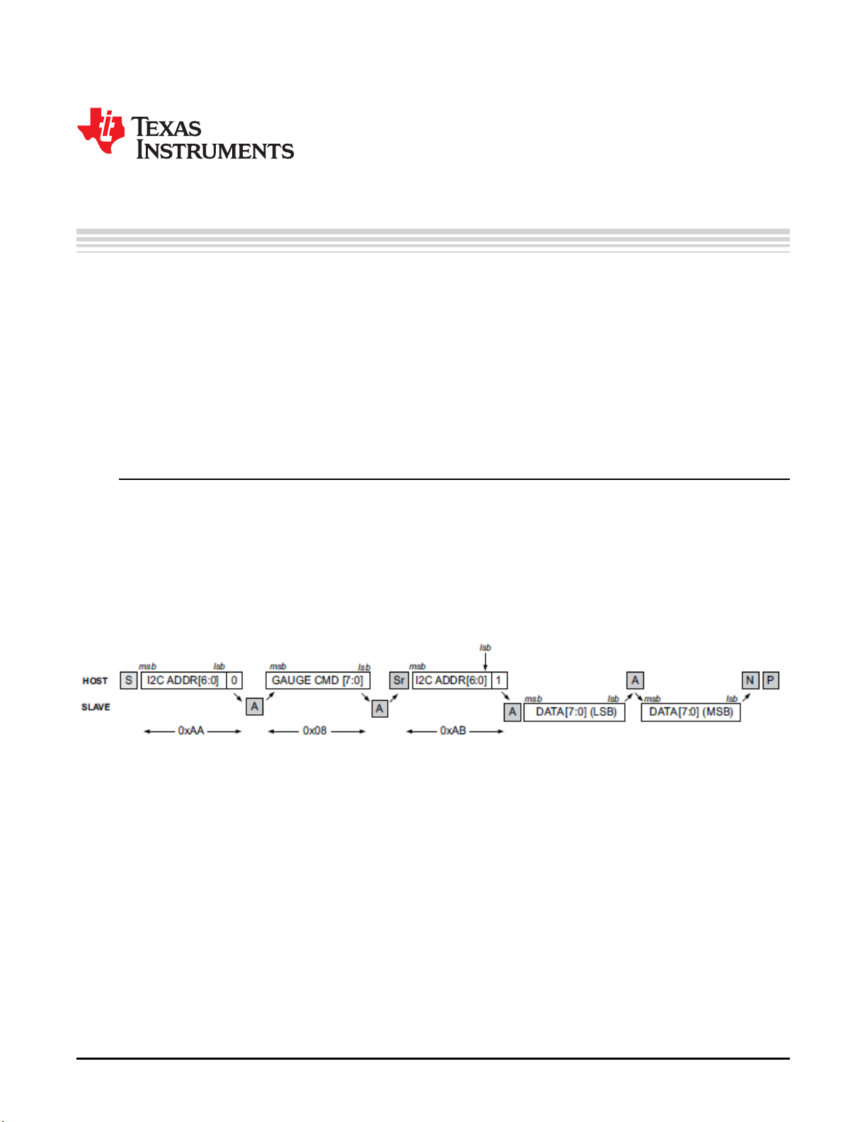
C commands are always initiated by the host with a START (S) bit sequence, immediately followed by a
7-bit I
2
C address with the most-significant bit (MSB) sent first. An eighth bit of 0 is sent by the host,
indicating that the next byte to be sent will be a write to the gauge. For the bq34xxx series and bq35xxx
series of parts, these 8 bits form the byte 0xAA. Once the start bit and address byte have been
successfully received by the gauge, the gauge responds with an ACKNOWLEDGE (A) bit sequence. The
gauge is now ready for the subsequent command directive from the host. Further descriptions of the
control bit sequences are presented in the Glossary: Control-Bit-Sequence Definitions.
Figure 1. Simple I
2
C Command Transaction Sequence
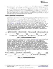
After the successful transmission of the I
2
C address and read or write bit, the gauge command code can
be sent by the host, in this case 0x08 for the Voltage( ) command. The command code is actually a base
address location within the gauge and must not be confused with the I
2
C address for the gauge. Once this
location is sent by the host, the gauge responds by sending an ACKNOWLEDGE bit sequence and then
executing the corresponding command subroutine. Even though two-byte locations are used for many
gauge commands, writing to only the single byte is required to start gauge command processing. In this
case, only 0x08 was written to the gauge, even though the command consists of the two consecutive
command bytes 0x08 and 0x09. Most commands consist of two bytes, because the data is returned to
these command locations and are also two bytes – the least-significant byte (LSB) is stored in the lower
address (0x08), whereas the MSB is stored in the higher address (0x09). Like the I
2
C address data, the
gauge command is sent MSB-first.