

herunterladen

© Semiconductor Components Industries, LLC, 2016
August, 2016 - Rev. 3
1 Publication Order Number:
AND9319/D
AND9319/D
DVK Use as a Sniffer Tool
Introduction
When dealing with RF systems it is often necessary to
investigate the packet data transmitted by an existing device.
If the parameters of the physical layer (frequency, datarate
and modulation) are known, the ON Semiconductor DVK
(DVK−2 as well as F143−MINI−DVK) can be used to
investigate the packet data.
This document describes how to display the data
transmitted by a given device using the ON Semiconductor
DVK and the AX−RadioLAB software.
Setup
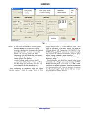
Create a new AX−RadioLAB Project. Make sure “RX
continuous” mode is selected.
In the Kit Configuration panel: Select DVK−2 or
F143−MINI−DVK according to your hardware. Make sure
“Output on debug link” is enabled.
In the PHY panel: Configure the known physical
parameters. Disable all encodings if unsure.
Finally the SYNC WORD or Start Frame Delimiter (SFD)
has to be configured in the framing panel. It should be
understood, that the receiver is continuously running and
there is no triggering on RF energy. The receiver is thus
continuously receiving random data from the noise except
for the very moments when your device is transmitting.
However, the received data is discarded by the receiver
unless the configured SYNC WORD is matched. After
matching the configured SYNC WORD a configurable
number of data data bytes is received into the radio FIFO.
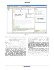
The microcontroller will then display the data via the debug
link interface.
If you happen to know the SYNC WORD transmitted by
your device you can simply enter it into the SYNC WORD
field of the framing panel and select the right length in the
“Syncword length” field. Note that the representation of the
SYNC WORD field in the framing panel is always MSB
first. (The MSB first option in the framing panel only affects
the fields after the SYNC WORD.)
If you don’t know the SYNC WORD used by your device
it is recommended to trigger on the preamble. In most cases
the device will transmit a series of 10101010 as a preamble.
One option is to configure the matching of a 32 bit SYNC
WORD of 55:55:55:55 or AA:AA:AA:AA. Those 32 bit
sequences are unlikely to appear in the noise and thus the
receiver will only trigger if preamble is received. The data
received into the radio FIFO consists of more preamble bits
appearing after the match, the transmitted SYNC WORD
and the transmitted payload. The drawback is, that the exact
trigger position inside the preamble is not well defined this
way. Thus each received packet will be preceeded by an
arbitrary number of preamble bits, which is inconvenient. A
more clever approach is to configure matching a 32 bit
SYNC WORD of 55:55:55:54 or AA:AA:AA:AB. (Try
both!) Matching 0101…010100 or 1010…101011, i.e. the
end of the preamble, will match a well defined point in the
bit stream. This prevents each received packet from being
displayed arbitrarily bit−shifted. However, the matching
will eat one or more bits of the transmitted SYNC WORD
(depending on the exact SYNC WORD). Thus the packet
will not be displayed in a byte synchronized manner. The
synchronization can be shifted by inspecting the received
data and configuring the SYNC WORD field to match n
more bit from the beginning of the received data. (At the
expense of n bits of the 0101 sequence, since matching is
restricted to 32 bit.) Note: The representation of the SYNC
WORD in the framing panel is always MSB first. For
dealing with the SYNC WORD as just described it is
therefore convenient to represent the received data MSB
first as well. This is achieved by checking “send MSB first”
in the framing panel. Note: with zero a priori knowledge
about the packet it may be impossible to determine the
borders between preamble, SYNC WORD and actual
packet.
Address matching and length byte should be disabled.
MAC header length should be set to 0. The DATA field of
the framing panel should contain N arbitrary bytes. This
causes the receiver to receive fixed length packets of N
bytes. CRC checking should be off.
www.onsemi.com
APPLICATION NOTE
Verzeichnis