
herunterladen
AN431
Document number: DS37414 Rev. 3 - 2
1 of 13
www.diodes.com
April 2015
© Diodes Incorporated
AN431
A Product Line of
Diodes Incorporated
ADJUSTABLE PRECISION SHUNT REGULATORS
Description
The AN431 series ICs are three-terminal adjustable shunt regulators
with guaranteed thermal stability over a full operation range. These
ICs feature sharp turn-on characteristics, low temperature coefficient
and low output impedance, which make them ideal substitutes for
Zener diodes in applications such as switching power supply, charger
and other adjustable regulators.
The output voltage of these ICs can be set to any value between V
REF
(2.5V) and the maximum cathode voltage (36V).
The AN431 precision reference is offered in two voltage tolerance:
0.5% and 1.0%.
These ICs are available in SOT-23 package.
Features
Programmable Precise Output Voltage from 2.5V to 36V
High Stability under Capacitive Load
Low Temperature Deviation: 4.5mV Typical
Low Equivalent Full-range Temperature Coefficient with
20PPM/
o
C Typical
Low Dynamic Output Resistance: 0.15Ω Typical
Sink Current Capacity from 1mA to 100mA
Low Output Noise
Wide Operating Range of -40 to +125
o
C
Lead-Free Packages: SOT-23
Totally Lead-Free; RoHS Compliant (Notes 1 & 2)
Lead-Free Packages, Available in “Green” Molding Compound:
SOT-23
Totally Lead-Free & Fully RoHS Compliant (Notes 1 & 2)
Halogen and Antimony Free. “Green” Device (Note 3)
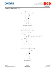
Pin Assignments
(Top View)
SOT-23
Applications
Charger
Voltage Adapter
Switching Power Supply
Graphic Card
Precision Voltage Reference
Notes: 1. No purposely added lead. Fully EU Directive 2002/95/EC (RoHS) & 2011/65/EU (RoHS 2) compliant.
2. See http://www.diodes.com/quality/lead_free.html for more information about Diodes Incorporated’s definitions of Halogen- and Antimony-free, "Green"
and Lead-free.
3. Halogen- and Antimony-free "Green” products are defined as those which contain <900ppm bromine, <900ppm chlorine (<1500ppm total Br + Cl) and
<1000ppm antimony compounds.
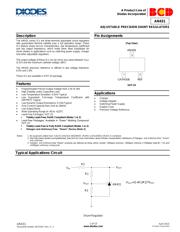
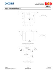
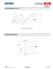
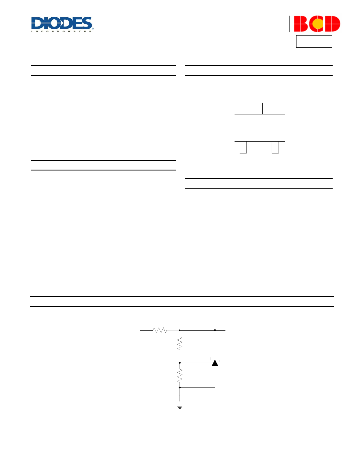
Typical Applications Circuit
V
IN
V
OUT
R1
R2
V
REF
AN431
R3
Shunt Regulator
3
21
ANODE
CATHODE REF
V
OUT
=(1+R1/R2)*V
REF
Verzeichnis
- ・ Konfiguration des Pinbelegungsdiagramms on Seite 1
- ・ Abmessungen des Paketumrisses on Seite 11
- ・ Paket-Footprint-Pad-Layout on Seite 12
- ・ Teilenummerierungssystem on Seite 10
- ・ Markierungsinformationen on Seite 10
- ・ Blockdiagramm on Seite 3
- ・ Typisches Anwendungsschaltbild on Seite 1 Seite 2 Seite 3
- ・ Technische Daten on Seite 4
- ・ Anwendungsbereich on Seite 1 Seite 2 Seite 3
- ・ Elektrische Spezifikation on Seite 5 Seite 6 Seite 7 Seite 8 Seite 9