
herunterladen
AN-913
APPLICATION NOTE
One Technology Way • P. O. Box 9106 • Norwood, MA 02062-9106, U.S.A. • Tel : 781.329.4700 • Fax: 781.461.3113 • www.analog.com
Isolating I
2
C Interfaces
by Ronn Kliger
Rev. 0 | Page 1 of 8
INTRODUCTION
The Inter-Integrated Circuit (I
2
C®) bus is a two-wire bidirectional
bus used for low speed, short-distance communication between
integrated circuits. Developed by Philips
1
in the early 1980s for
use amongst ICs on a single board, I
2
C today is increasingly
being used in multiboard applications as new bus extensions
and control devices help overcome the original 400 pF maxi-
mum allowable load capacitance.
Often, in multicard applications such as blade servers or
digitally-controlled power converters, it is desired that
each interface be isolated to allow for trouble-free card
insertion/removal or for safety considerations. However,
isolating I
2
C interfaces is complicated by the bidirectional
nature of the I
2
C bus. This characteristic is not compatible
with the unidirectional behavior of optocouplers.
This application note provides a brief overview of the I
2
C bus
(focusing on its physical layer), discusses the challenges in
isolating I
2
C interfaces, and describes iCoupler® solutions for
isolating I
2
C interfaces.
I
2
C OVERVIEW
The I
2
C interface is defined by The I
2
C-Bus Specification,
Version 2.1, January 2000 (NXP Semiconductors). This
interface consists of two wires: serial data (SDA) and serial
clock (SCL). These wires convey information to and from
devices connected to the bus, each of which is identified by
a unique address. At any instance, a device can be a transmitter
or a receiver although some devices may operate only as one or
the other. In addition, at any instance, a device can be a master
or a slave. A master is a device that initiates a data transfer by
addressing another device while a slave is a device that is
addressed by a master.
The I
2
C bus allows for more than two devices to be connected
to it and for multiple master/slave relationships to exist. The
operation of the bus under such circumstances is defined by
an arbitration procedure defined in the I
2
C standard.
Note that the master/slave designations are independent of
whether a device is a transmitter or a receiver. For example, in
a sequence in which a master initiates a data transfer from a
slave, it is first a transmitter (as it addresses the slave), then
a receiver (as it receives the data from the slave), and then a
transmitter again (as it terminates the transfer). In a similar
fashion, the slave is first a receiver, then a transmitter, and
then a receiver.
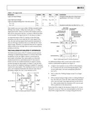
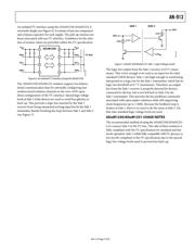
The I
2
C bus operates on the principle of open-drain/open-
collector wire-AND functionality (see Figure 1). All devices
connected to the bus must be at a logic high state in order for
the bus to be at a logic high state. When this situation exists
for both the SDA and SCL lines, the bus is considered to be free
for a device to initiate a data transfer. Both SDA and SCL are
bidirectional lines to support the ability of devices to take on
both transmitter and receiver roles.
1
In 2006, Philips spun out their semiconductor operations (including their I
2
C
portfolio) to create a new independent company called NXP Semiconductors.
DATAN2
OUT
DATA
IN
SCLKN2
OUT
SCLK
IN
SCLK
DATAN1
OUT
DATA
IN
SCLKN1
OUT
SCLK
IN
SCLK
R
P
PULL-UP
RESISTORS
SDA (SERIAL DATA LINE)
SCL (SERIAL CLOCK LINE)
DEVICE 1 DEVICE 2
R
P
+
V
DD
06751-001
Figure 1. I
2
C Bus