
herunterladen
AN-1407
Application Note
One Technology Way • P. O. Box 9106 • Norwood, MA 02062-9106, U.S.A. • Tel: 781.329.4700 • Fax: 781.461.3113 • www.analog.com
ADSP-CM402F/ADSP-CM403F/ADSP-CM407F/ADSP-CM408F/ADSP-CM409F
Pulse Width Modulator in AC Motor Control Applications
by Dara O’Sullivan, Jens Sorensen, and Aengus Murray
Rev. 0 | Page 1 of 12
INTRODUCTION
This application note introduces the main features of the ADSP-
CM402F/ADSP-CM403F/ADSP-CM407F/ADSP-CM408F/ADSP-
CM409F pulse width modulator (PWM) and use in 3-phase ac
motor control applications. The PWM peripheral is capable of
driving inverters for a variety of power converter applications,
including standard 3-phase ac inverters, multilevel ac inverters,
and a variety of dc-to-dc converters. There are three PWM
peripheral blocks, each with four pairs of PWM outputs. The
controller supports all ac motor types and includes features that
support six-step control of brushless dc (BLDC) motors and
control of switched reluctance motors. This application note
focuses on 3-phase ac inverter control. For more information
about the full range of PWM controller features and configuration
registers, see the ADSP-CM40x Mixed-Signal Control Processor
with ARM Cortex-M4 Hardware Reference Manual and the docu-
mentation within the ADSP-CM40x Enablement Package software.
3-PHASE MOTOR CONTROL
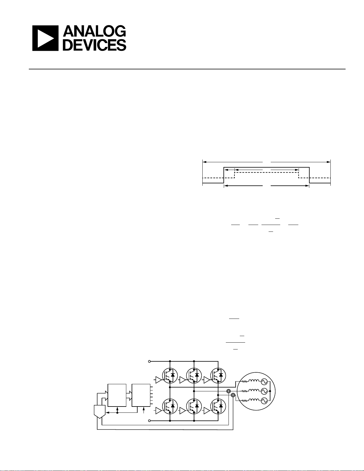
The 3-phase voltage fed inverter, shown in Figure 2, drives a 3-
phase ac motor under the control of a PWM modulator connected
to a microcontroller central processing unit (CPU). The inverter
produces fixed frequency variable duty cycle waveforms modulated
with the target motor voltage and frequency. The motor windings
filter the high frequency components and motor current is at
the fundamental frequency with some residual ripple. The inverter
behaves as a variable frequency ac source with outputs ranging
from 0 to V
DC
, centered around V
DC
/2. The CPU executes a
digital control algorithm that calculates required inverter voltages
at the switching frequency. Typically, the control algorithm also
requires winding current feedback and the PWM modulator
provides synchronizing triggers to the CPU, analog-to-digital
converter (ADC), and other microcontroller peripherals.
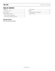
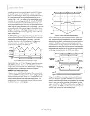
The inverter waveform, shown in Figure 1, is a center-based
PWM waveform where the on period grows or shrinks around
the midpoint of the switching waveform.
Figure 1. Inverter Switching Waveform
The inverter output as a function of the on time is
2
2
2
2
DC
ON
DCON
DC
V
T
T
t
V
T
t
VV
+
−
=
=
(1)
where t
ON
is the on time of the PWM output, defined in Figure 2.
When driving a balanced 3-phase load such as an ac motor,
setting 50% duty cycle to all three phases applies 0 V across the
windings. Therefore, the inverter output of V
DC
/2 at 50% duty cycle
corresponds to zero voltage. Then duty cycles greater than 50%
produce positive voltages and duty cycles less than 50% produce
negative voltages. This ac voltage, V
AC
, scales according to a
modulation function (m). This equation defines the operation
of the PWM modulator:
2
DC
AC
V
mV =
(2)
Where m =
2
2
T
T
t
ON
−
.
Figure 2. 3-Phase AC Motor Drive
t
ON
m
T
T/2
14690-002
AC MOTOR
FEEDBACK
V
DC
+
PWM
V
DC
–
CPU
TRIP
SYNC
ADC
AH BH CH
AL
V
A
V
B
BL CL
14690-001