


herunterladen
REV. 0
AN-619
APPLICATION NOTE
One Technology Way
•
P.O. B
ox
9106
•
N
orwood
, MA 02062-9106
•
T
el
TelT
: 781/329-4700
•
F
ax
:
781/326-8703
•
www.analog.com
Using the ADN8810 Demo Board v2.0
by Troy Murphy and Chris Kung
OVERVIEW
The ADN8810 is a 12-bit, high output current D/A converter
that is controlled through a serial peripheral interface
(SPI). The device can be used as a current source for tunable
lasers or other precision high output current applications,
like 4–20 mA control loops. Refer to the ADN8810 data
sheet for technical speci cations.
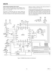
The demo board for the ADN8810 provides a complete
solution, which includes a precision 4.096 V reference
(ADR292), simple connections for power supplies and
output load, and 25-pin D-sub plugs to connect to the
parallel port of a computer.
Multiple devices can be controlled from one computer
by daisy-chaining demo boards together. Use jumpers to
short header pins on the board to set the address code for
the ADN8810. Eight address codes are available, allow-
ing separate control of eight demo boards from a single
computer.
POWER SUPPLY CONNECTION
The power supply connection block is located at the top
of the demo board. The board can be powered from two
con gurations: all single supplies or positive and negative
supplies. Table I shows the required supply voltages.
Table I. Required Power Supply Voltages
Single-Supply (V)
Split-Supply (V)
AVDD
5
3
PVDD
3.0 to 3.3
1.0 to 1.3
GND
0
0
VSS
0
–2
Note that VSS must be connected to 0 V for single-supply operation.
VSS and GND are not directly connected on the demo board.
Most applications can use the single-supply con guration.
However, some laser diodes require a connection to –2 V
for proper operation. These applications require a negative
VSS supply voltage.
LASER DIODE OR LOAD CONNECTION
The laser diode or load connection block is located at the
bottom of the board. Output current from the ADN8810
comes out of LD+ and returns to LD–. The ADN8810 can
only source current. The output voltage can typically go
as high as 2.5 V. This is indicated in the data sheet as
output compliance voltage. The LD+ output cannot sink
current.
The LD– terminal is connected directly to VSS on the
board. If operated from a single supply, VSS must be
set to 0 V.
SHUTDOWN CONTROL AND ADDRESS HEADERS
The SHUTDOWN terminal is labeled
SD
and is located at
SD and is located at SD
the bottom of the demo board. No connection is required
to this terminal. A pull-up resistor is provided on the
board, activating the ADN8810 even with no interface cable
connected. The green LED indicates an active device.
Shutdown for the ADN8810 is also controlled from the
demo board software. Although the demo board includes
a 100
protection resistor, forcing a voltage on the SHUT-
DOWN terminal with the interface cable still connected
could damage the parallel port on your computer.
INTERFACING WITH AN EXTERNAL MICROCONTROLLER
The ADN8810 demo board can be controlled with an
external microcontroller or DSP. Solder a wire with the
appropriate logic signal to the right side of resistors R1
through R6, located toward the right of the demo board.
These resistors are labeled with their respective pin names.
The shutdown signal can be connected directly to the
SHUTDOWN terminal at the bottom of the demo board.
BOARD FAULT AND ACTIVE INDICATION
The red LED indicates an output FAULT and will illumi-
nate if the output (labeled LD+) is short-circuited to GND,
VSS, or LD–. This LED also turns on if the output voltage
is greater than PVDD – 0.6, since this indicates a potential
open-circuit to the load.
The green LED turns on if the ADN8810 is active. Power
must be supplied to the demo board and the
SD
pin must
SD pin must SD
be logic high for the device to be active. A pull-up resistor
is included on the demo board, allowing the ADN8810 to
remain active even with no parallel port cable connected.