
herunterladen
AN-1024
APPLICATION NOTE
One Technology Way • P. O. Box 9106 • Norwood, MA 02062-9106, U.S.A. • Te l: 781.329.4700 • Fax: 781.461.3113 • www.analog.com
How to Calculate the Settling Time and Sampling Rate of a Multiplexer
by Theresa Corrigan
Rev. 0 | Page 1 of 4
INTRODUCTION
This application note describes how to calculate the settling
time of a switch and a multiplexer switch. It also discusses
how to calculate the maximum sampling rate for a multiplexer.
CALCULATING THE SETTLING TIME OF A SWITCH
OR MULTIPLEXER
A rudimentary way of calculating how long a switch or
multiplexer takes to settle can be estimated by calculating the
RC for the device, that is, R
ON
× C
D
, and multiplying by the
number of time constants for required system accuracy. This
is added to the switch timing, T
ON
, T
OFF
, or T
TRANSITION
, for the
switch or multiplexer.
Time to Settle = Switching Timing + (R
ON
× C
D
×
No. of Time Constants)
where:
R
ON
is the switch on resistance.
C
D
is the switch drain capacitance.
No. of Time Constants = −ln (% error/100).
The settling time can be calculated because the response is a
function of the switch and circuit resistances and capacitances.
One can assume that this is a single-pole system and calculate
the number of time constants required to settle to the desired
system accuracy as shown in Table 1.
Table 1. Number of Time Constants Required to Settle to
1 LSB Accuracy for a Single-Pole System
Resolution,
No. of Bits
LSB (%FS)
No. of Time Constants =
−ln (% Error/100)
6 1.563 4.16
8 0.391 5.55
10 0.0977 6.93
12 0.0244 8.32
14 0.0061 9.70
16 0.00153 11.09
18 0.00038 12.48
20 0.000095 13.86
22 0.000024 15.25
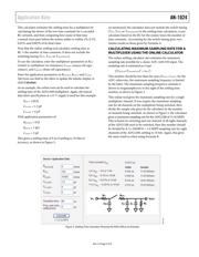
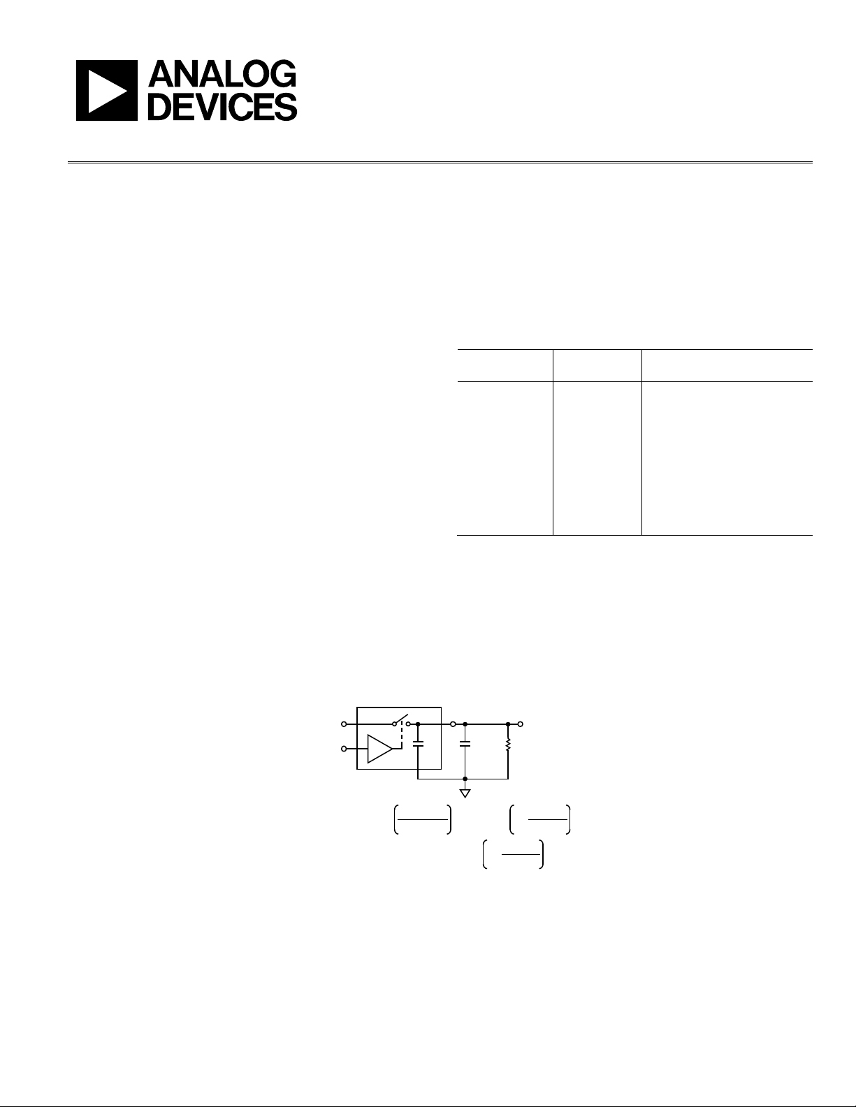
The switch dynamic transfer function is shown in Figure 1. This
shows a single switch channel in a typical application setup and
the key parameters that come into effect during switching. The
equations for calculating the settling time for a switch when
going from the on-to-off position and the off-to-on position
are shown in Figure 1.
V
IN
S D
LOGIC
INPUT
C
D
C
LOAD
R
LOAD
V
OUT
OFF-TO-ON:
t
SETT
=
t
ON
+(C
LOAD
+ C
D
)–ln
R
ON
× R
LOAD
R
ON
+ R
LOAD
%ERROR
100
ON-TO-OFF:
t
SETT
=
t
OFF
+(R
LOAD
)(C
LOAD
+ C
D
)–ln
%ERROR
100
NOTES
1. SETTLING TIME IS THE TIME REQUIRED FOR THE SWITCH OUTPUT
TO SETTLE WITHIN A GIVEN ERROR BAND OF THE FINAL VALUE.
08231-001
Figure 1. Dynamic Switch Transfer Function—Settling Time