
herunterladen
AN-797
APPLICATION NOTE
One Technology Way • P.O. Box 9106 • Norwood, MA 02062-9106 • Tel: 781/329-4700 • Fax: 781/461-3113 • www.analog.com
INTRODUCTION
The EVAL-PRAOPAMP-4R/4RU is an evaluation board
which accommodates quad op amps in SOIC and TSSOP
packages. It is meant to provide the user with multiple
choices and extensive exibility for different applica-
tions circuits and congurations.
This board is not intended to be used with high fre
quency
components or high speed ampliers. However, it pro
vides
the user with many combinations for various circuit
types including active lters, instrumentation ampliers,
composite amplier, and external frequency compensa-
tion circuits. For examples of application circuits refer to
ADI amplier data sheets under the applications section.
This application note will present different implementa-
tions of lter design using quad ampliers.
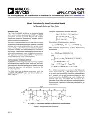
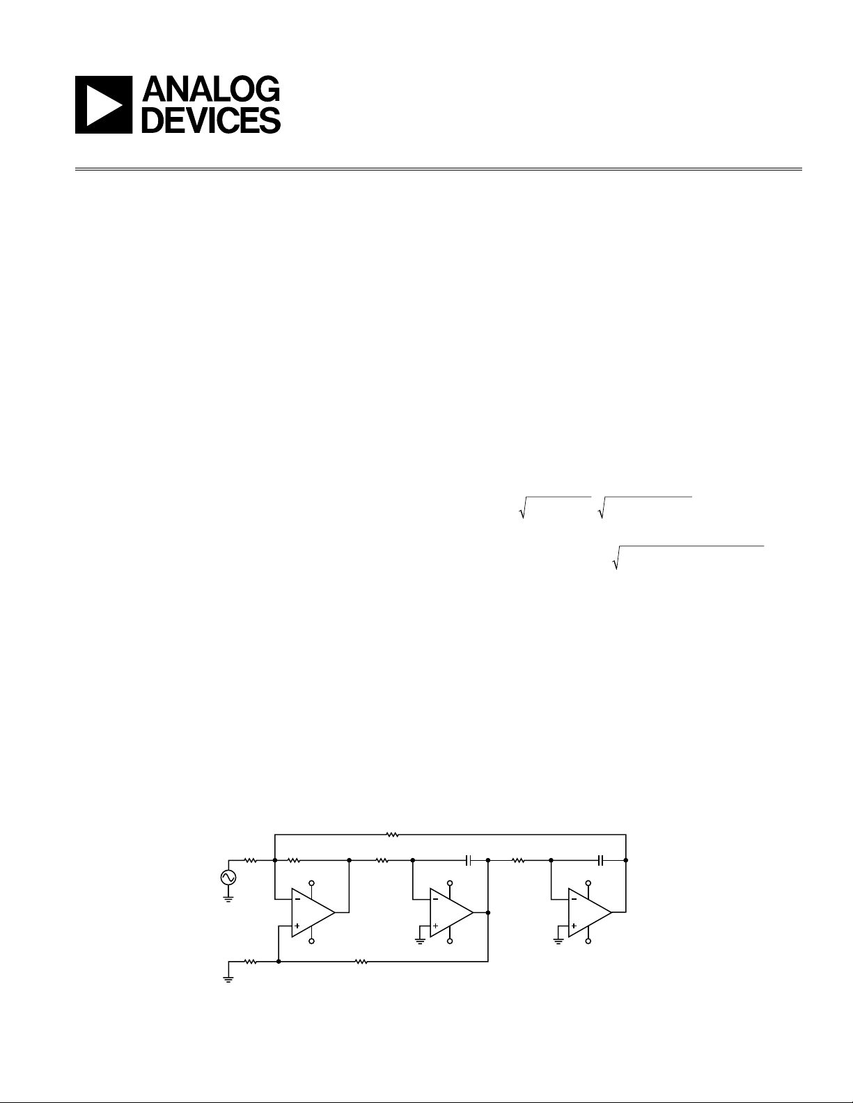
STATE VARIABLE FILTER (INVERTING)
The SV lter uses two integrators and a summing am
plier
to provide second-order low-pass, band-pass, and high-
pass responses. A fourth op amp can be used to combine
the existing responses and synthesize the notch or the
all-pass responses.
This lter circuit can be easily constructed using the
quad EVAL_PRAOPAMP board and following the sche-
matic in Figure 1.
Quad Precision Op Amp Evaluation Board
by Giampaolo Marino and Steve Ranta
Using the superposition principle, we write
V R6 / R4 V R4 R V
R4/ R6 R4/ R
R /
R5
V
HP JUMP LP
JUMP
JUMP1
BP
=
(
)
(
)
+
+
(
)
+
(
)
+
(
)
– –
/
/
1
1
1
Since A2 and A3 are integrators, we have:
V R8 C6s V V / R13 C8 V
BP HP LP BP
=
(
)
=
(
)
– / –1 1and
After extended simplications we have the following
expressions:
ω
o
and
=
(
)
(
)
=
+
(
)
(
)
+ +
(
)
= =
+
(
)
+ +
(
)
=
R4 R R8 C6 R13 C8
Q
R R5 R4 R8 C6/R R13 C8
R4/ R6 R4/R
H R4 R6 H R R
5
R6 R R6 R4 H R R6
JUMP
JUMP1 JUMP
JUMP
OHP OBP JUMP1
JUMP OLP JUMP
/ /
/ /
– / , /
/
/ / , –
/
1
1
1
1
From the above expressions we observe that Q depends
on the resistor ratio R
JUMP1
/R5. We therefore expect Q
to be much less sensitive to resistance tolerances and
drift. Indeed, with proper component selection and
circuit construction, the SV lter can easily yield de
pend-
able
Qs in the range of hundreds. For best results, it is
ad
visable to use metal lm resistors and polystyrene or
polycarbonate capacitors, and properly bypass the op
amp supplies.
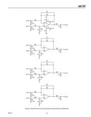
V+
V–
V
LP
= V
OUT
C
V+
V–
V
BP
= V
OUT
B
V+
V–
V
HP
= V
OUT
A
V
CC
A1
1
2
3
V
EE
V
CC
A2
7
6
5
V
EE
V
CC
A3
8
9
10
V
EE
C8C6
R13R8R4R6
R
JUMP
*
R
JUMP1
*
R5
–V
IN
A
*R
JUMP
AND R
JUMP1
IS AN EXTERNAL COMPONENT, NOT PROVIDED ON THE APPLICATION BOARD.
Figure 1. State Variable Filter (Inverting)
REV. 0