
herunterladen
AN-1321
APPLICATION NOTE
One Technology Way • P. O. Box 9106 • Norwood, MA 02062-9106, U.S.A. • Tel : 781.329.4700 • Fax: 781.461.3113 • www.analog.com
Common-Mode Transients in Current Sense Applications
by Kristina Fortunado
Rev. 0 | Page 1 of 2
INTRODUCTION
Current sense amplifiers are used in a variety of applications,
such as motor or solenoid control, load current monitoring, and
fault detection. In such applications, it is typical for the input
common-mode voltage to swing from ground to a certain high-
side supply. However, while a user may work with the assumption
that the input common-mode swings are limited to this high-
side supply, there are transient voltages that must be considered.
The result of these transients is that a supposed low voltage
application tends to appear as a high voltage application, and
the current sense amplifier must be robust enough to handle
these occurrences.
TRANSIENT VOLTAGES IN A MOTOR DRIVE
CIRCUIT
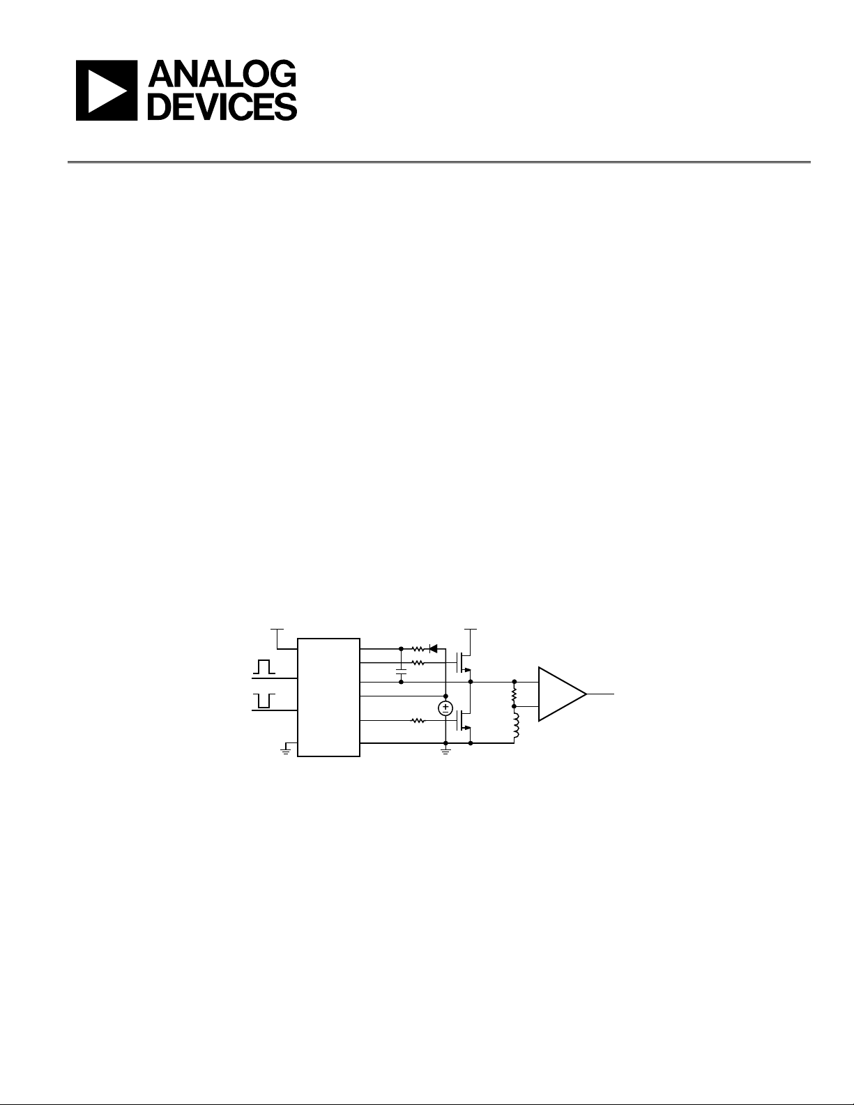
One can consider a motor drive circuit to gain insight into these
transient voltage events. The circuit shown in Figure 1 uses the
ADuM3223 to drive the gates of two MOSFETs in a half-bridge
configuration. The inputs of the ADuM3223 are driven with
inverted pulse-width modulation (PWM) signals with duty
cycles of 50%, enabling switching between the two MOSFETs.
The node between the emitter of the high-side FET and the
collector of the low-side FET is the half-bridge point of the
motor drive circuit. This node becomes the connection to the
shunt resistor, R
SH
, and the motor load, represented by an
inductance, M. In this circuit, the AD8418, a current sense
amplifier, is used to monitor the differential voltage across the
shunt resistor. Since this differential voltage is typically a small
value in the range of millivolts, the common-mode voltage seen
by the current sense amplifier is essentially the voltage at the
half-bridge point, and is denoted as V
CM
in Figure 1.
When the low-side FET turns on, the half-bridge point is pulled
down to ground. When the low side FET switches off and the
high side FET turns on, the half-bridge point switches to the
bus voltage, V
BUS
. It is during this momentary switching that
transients become apparent. These transients are caused by the
fast switching speed of the load, along with the reactive nature it
presents to the driver.
Fi
gure 1. Motor Drive Circuit with the ADuM3223 and the AD8418
V
DD1
V
BUS
V
CM
R
SH
M
ADuM3223
AD8418
V
DDB
V
OUT
V
DDA
V
OA
V
IA
V
IB
V
OB
GND
1
GND
B
GND
A
12606-001