

herunterladen
AN-1069
APPLICATION NOTE
One Technology Way • P. O. Box 9106 • Norwood, MA 02062-9106, U.S.A. • Te l: 781.329.4700 • Fax: 781.461.3113 • www.analog.com
Zero Latency for the AD7190, AD7192, AD7193, AD7194, and AD7195
by Mary McCarthy and Adrian Sherry
Rev. 0 | Page 1 of 4
INTRODUCTION
The ADCs listed above are ultralow noise, 24-bit, sigma-delta
(Σ-Δ) analog-to-digital converters with PGA. These products
include a digital filter as an integral part of the converter. There
are a number of ways to configure this filter, one which allows
it to operate without the settling time latency commonly
associated with Σ-Δ ADCs. This application note describes this
behavior, and compares it to the more conventional filtering
also available on these ADCs.
ZERO-LATENCY MODE
These ADCs include an option to place the filter into a zero-
latency mode or single cycle settling mode. In this mode, the
ADC output period is always equal to the filter settling time.
Therefore, the ADC’s output data rate is the same regardless
of whether the converter is converting on a single channel or
whether the input channel is periodically changed.
By simply setting bit SINGLE in the Mode register to 1, the
ADC operates as a zero-latency ADC.
The ADCs discussed in this application note have two filter
types: a sinc
3
filter and a sinc
4
filter (selectable using the SINC3
bit in the Mode register).
In zero-latency mode, the output data rate is equal to
f
ADC
= f
CLK
/(3072 × FS[9:0])
for the sinc
3
filter and
f
ADC
= f
CLK
/(4096 × FS[9:0])
for the sinc
4
filter
where:
f
CLK
is the master clock (4.92 MHz nominal).
FS[9:0] is the decimal equivalent of the code in Bits FS9 to FS0
of the Mode register.
This is the equation for the output data rate when chop is
disabled. Note that chop is assumed to be disabled in this
application note, unless otherwise stated.
In both cases, the settling time is equal to
t
SETTLE
= 1/f
ADC
for the sinc
3
or sinc
4
filter.
Table 1 and Table 2 provide examples of output data rates and
the corresponding FS values for the sinc
3
and sinc
4
filters.
Table 1. Examples of Output Data Rates and the
Corresponding Settling Time (Sinc
4
Filter)
FS[9:0] Output Data Rate (Hz) Settling Time (ms)
480 2.5 400
96 12.5 80
80 15 66.6
12 100 10
5 240 4.17
1 1200 0.83
Table 2. Examples of Output Data Rates and the
Corresponding Settling Time (Sinc
3
Filter)
FS[9:0] Output Data Rate (Hz) Settling Time (ms)
480 3.3 300
96 16.7 60
80 20 50
16 100 10
5 320 3.125
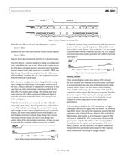
Channel Change
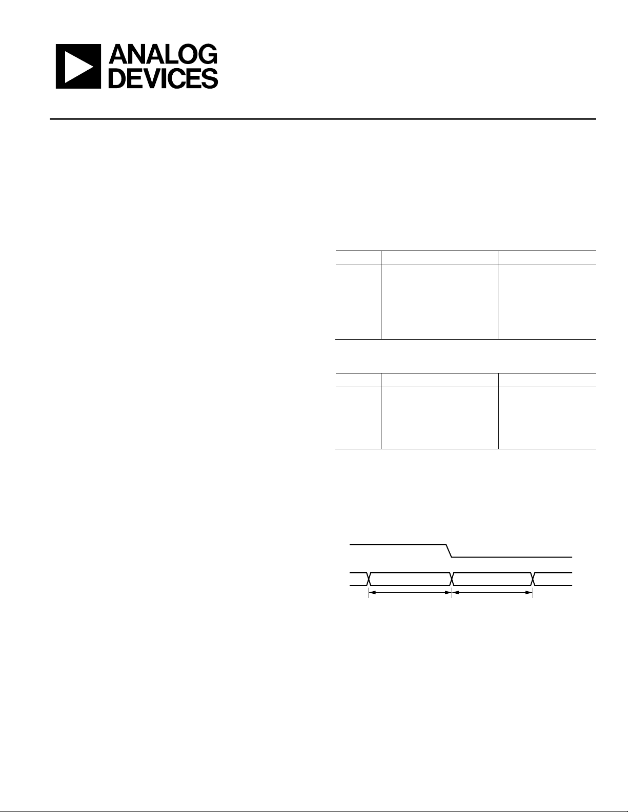
Figure 1 shows the response of the ADC to a channel change
when zero-latency mode is enabled. From Figure 1, the conver-
sion time when converting on Channel A and Channel B is the
same. In addition, there is no additional delay when switching
from Channel A to Channel B.
CHANNEL
ZERO-LATENCY
CHANNEL B
1/f
ADC
CHANNEL A
CHANNEL A CHANNEL A CHANNEL B
08939-001
Figure 1. Channel Change (Zero-Latency Mode)
Analog Input Step Change on Selected Input
If a step change occurs in the analog input voltage, the ADC
does not detect such a change and continues to output all
conversions. It is possible that the next conversion will not fully
reflect the change in the analog input as the complete settling
must elapse after the step change (see Figure 2). In this case, it
is the second conversion after the channel change that fully
reflects the change in the analog input. Therefore, zero latency
does not ensure that all conversions are completely settled.